Figure 4-11: delay trigger – ADLINK DAQe-2006 User Manual
Page 55
Operation Theory
43
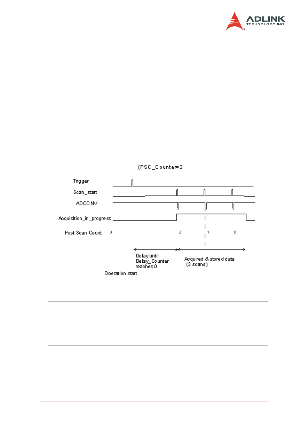
Delay Trigger Acquisition
Use delay trigger acquisition in applications where you want to
delay the data collection after the occurrence of a specified trig-
ger event. The delay time is controlled by the value, which is
pre-loaded in the Delay_counter (16-bit). The counter counts
down on the rising edge of the Delay_counter clock source
after the trigger condition is met. The clock source can be soft-
ware-programmed either by the TIMEBASE clock (40 MHz) or
A/D sampling clock (TIMEBASE / SI_counter). When the count
reaches 0, the counter stops and the card starts to acquire
data. The total acquired data length = number of enable-chan-
nel * PSC_counter.
Figure 4-11: Delay trigger
NOTE
When the Delay_counter clock source is set to TIME-
BASE, the maximum delay time = 216/40M s = 1.638ms,
and the source is set to A/D sampling clock, the maxi-
mum delay time may be higher than 216 * SI_counter /
40M.