Aiphone LAF-20 User Manual
Page 4
Attention! The text in this document has been recognized automatically. To view the original document, you can use the "Original mode".
The following diagram illustrates an intermixed LAP system. All stations connected to the
BG-IAC/PG-KC will receive all-call announcements and BGM. Substations must be connected to the
BG-IAC/PG-KC thru a 15 mfd bipolar capacitor as shown (if BGM/all-call is desired), or the system
will not work.
WIRING DIAGRAM #1
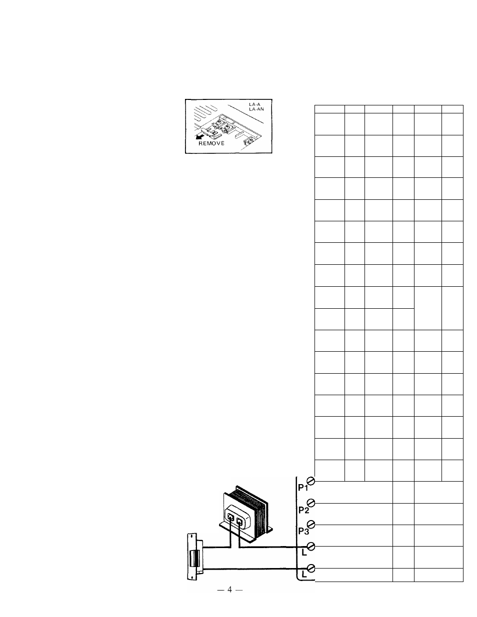
NOTE: Remove the shorting link attached to the (E) and ( —)
terminals on all substations
as shown if your system
uses 2 or more masters. In
this case, 2 common and 1
individual wire per sub are
required.
SUB 1
0
.0
0
LA-A
SUB 2
,0
r0
■0
LA-A
SUB 3
,0
0
0
LA-A
MASTER 1
LAF-20S
MASTER 2
LAF-20
NOTE: Separate AC trans
former (PT-1210) is
required to power
door release. Wiring
should be separated
from communication
wiring to avoid noise
from activated door
release.
DOOR
STATION
r0
0
POWER SUPPLY
LA-0
PT-1210
TRANSFORMER
0
,0
PS-12C
EL-9S
.0
0
’ s
0
10
,0
A1
,0
A2
0
A8
0
0
A^
0
AlO
0
0
0
0
>0
MASTER 3
LAF-20S
MTSTER
LAF-20
ci
A
1^
o,
10
p
c*
2^
A
2^
P-
s
10^
10^
o>
c®
p
A1^
A1^
r>
A1^
_O
l
kP
A2^
P
S
kP
S
A3^
S
P
A8
A8^
A9^
A9
kP
P
AlO
Ok
AlO
AlO
P
20
O
l
10^
P
O
l
E0
Ok
_
O
l
_
O
l
_P
P
P-
P1^
_p
P2
Ok
P3^
Ok
P
4