Aiphone LAF-20 User Manual
Page 2
Attention! The text in this document has been recognized automatically. To view the original document, you can use the "Original mode".
INSTALLATION
Do not attempt to install your LAF master stations until you have read and thoroughly under
stand the installation instructions. Aiphone’s warranty is void if the system is installed in a manner
other than described in this manual.
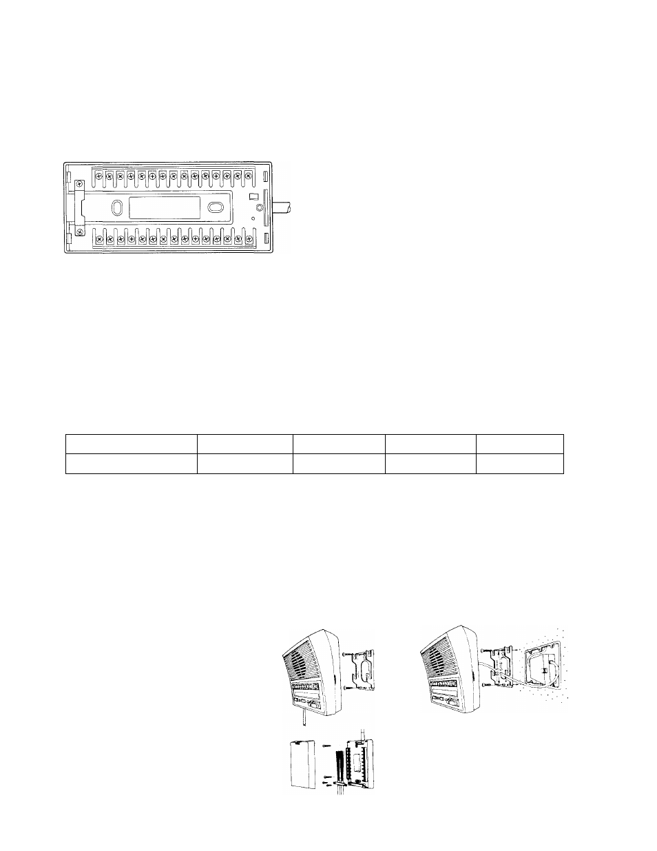
ACTUAL TERMINAL LOCATION
A3 A2 A1 L L 10 9
7 6 5 4 3 2
+ P3 P2 PI E R C A10A9 A8 A7 A6 A5 A4
1 - AlO : Connect to relative stations.
C
: Receiving a call and BGM.
-f , -
: Power supply connection.
E
; Common connection.
R
: Occupied light control.
L , L
: Door release contacts.
PI
: All-call control.
P2 , P3 : All-call output.
WIRING
Lay out your system in advance. Determine the exact location of each station, and make a
sketch showing the number of wires required from each station to the other stations. Assign station
numbers at this time.
Refer to the chart below and select the proper wire gauge to meet your specific distance
requirements.
AWG WIRE SIZE
24 AWG
22 AWG
20 AWG
18 AWG
DISTANCE
400'
650'
1000'
1600'
Begin your installation with master station All masters included in your system should be
connected and tested before beginning substation installation. Note the position of the (C) terminal on
each master station, and be sure that each station is wired correctly.
After installing your second station, we recommend the power supply be connected and a test
be made of all functions, calling and talking between each station. Unplug the power supply before
making any additional connections.
WALL MOUNTING INSTALLATION
1) Attach mounting bracket to wall
or box with supplied screws.
2) Mount station on bracket.
TERMINAL BOX INSTALLATION
1) Remove screw and cover as
shown.
2) Mount bottom case to wall or
box with supplied screws.
3) Wire terminals as necessary and
replace cover.
The Terminal box may be mounted
inside 3-gang box.
-
2