Aiphone LAF-20 User Manual
Page 3
Attention! The text in this document has been recognized automatically. To view the original document, you can use the "Original mode".
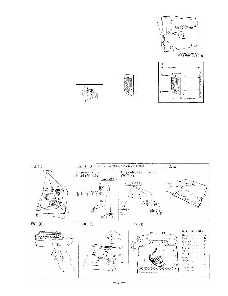
ADJUSTING VOLUME CONTROLS
Fingertip adjustment ensures pleasant communication at the
desired level all the time.
Use a screwdriver to adjust the call tone volume control to the
desired level.
LA-D INSTALLATION
1) Attach unit to a single gang box with the
screws provided.
2) When mounting to wall, wires may be
routed thru the top or bottom of the back
case. As shown, cut
out the thin part of
case when passing
wires thru top.
CUTOUT
BACK
VIEW
(TOP. BIGHT)
(
1
)
Screw (x21
PhJiltlliin
Connecting Gang
Js3 5 mm
1 (3-5/16")
INSTALLATION OF LAR-2 OPTIONAL HANDSET
1) Remove the 4 mounting screws on bottom of the master as shown in Fig. 1, and lift the plastic case
from the base.
2) Using a nipper or soldering iron, remove the jumpers between A & G, I & J, and K & L on the
printed circuit board as shown in Fig. 2.
3) Make a hole in the body of the base to pass the wires thru using a soldering iron, '/
4
" or 8mm drill
as shown in Fig. 3. If a soldering iron is used, clean away the burned plastic with a sharp knife as
shown in Fig. 4.
4) Route the wires into the base and mount the handset with screws provided as shown in Fig. 5.
5) Solder the 12 wires from the handset to the printed circuit board as shown in Fig. 6. Be sure the
wires are in the correct order.
6) Replace the plastic case and reinstall the mounting screws.