Step 6 — install accessories, Step 7 — complete electrical connections – Carrier 38AUZ User Manual
Page 9
9
Table 4 — Refrigerant Specialities Part Numbers.
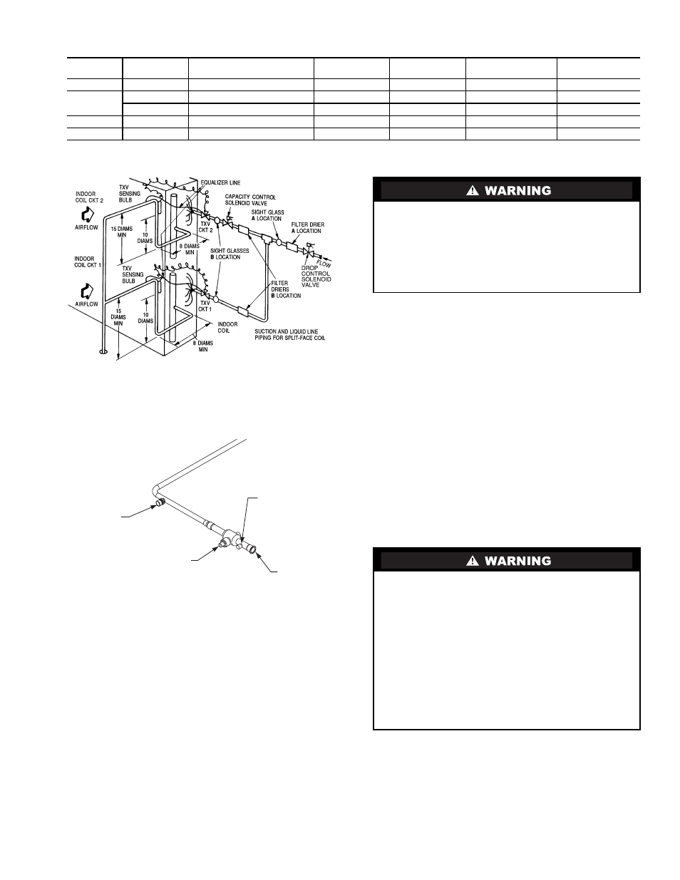
Fig. 5 — Location of Sight Glass(es)
and Filter Driers
Fig. 6 — Typical Piping Connection Assembly
Pressure-test all joints from outdoor unit connections over to
the evaporator coil, using nitrogen as pressure and with soap-
and-bubbles.
When pressure-testing is completed, remove the nitrogen
source at the outdoor unit service valves and re-install the two
Schrader valve cores. Torque the cores to 2-3 in-lbs (23-34
N-cm).
EVACUATION/DEHYDRATION — Evacuate and dehydrate
the connected refrigeration system (excluding the 38AU unit)
to 500 microns using a two-stage vacuum pump attached to the
service ports outside the 38AU service valves, following de-
scription in GTAC II, Module 4, System Dehydration.
PRELIMINARY CHARGE — Before starting the unit, charge
R-410A liquid refrigerant into the high side of the system
through the liquid service valve. The amount of refrigerant
added must be at least 80% of the operating charge listed in the
Physical Data table (Tables 1A and 1B, pages 4 and 5) LESS
the factory charge quantity (if factory shipping charge has not
been removed). Allow high and low side pressures to equalize.
If pressures do not equalize readily, charge R-410A vapor
(using special service manifold with expansion device) into the
suction line service port for the low side of system to assure
charge in the evaporator. Refer to GTAC II, Module 5,
Charging, Recover, Recycling, and Reclamation for liquid
charging procedures.
Step 6 — Install Accessories
Accessories requiring modifications to unit wiring should be
completed now. These accessories may include Winter Start
controls, Low Ambient controls, phase monitor, Compressor
LOCout. Refer to the instructions shipped with the accessory.
Step 7 — Complete Electrical Connections
NOTE: Check all factory and field electrical connections
for tightness. Field-supplied wiring shall conform with the
limitations of 63°F (33°C) rise.
Field Power Supply —
If equipped with optional Powered Convenience Outlet: The
power source leads to the convenience outlet's transformer
primary are not factory connected. Installer must connect these
UNIT
LIQUID LINE
SIZE (in.)
LIQUID LINE
SOLENOID VALVE (LLSV)
LLSV
COIL
SIGHT
GLASS
FILTER
DRIER
SUCTION LINE
ACCUMULATOR
38AUZ*07
3
/
8
200RB5T3M
AMG/24V
AMI-1TT3
P502-8304S*
S-7063S*
38AUZ*08
3
/
8
200RB5T3M
AMG/24V
AMI-1TT3
P502-8304S*
S-7063S*
1
/
2
200RB5T4M
AMG/24V
AMI-1TT4
P502-8304S
S-7063S*
38AUZ*12
1
/
2
200RB6T4M
AMG/24V
AMI-1TT4
P502-8307S*
S-7063
38AUZ*14
5
/
8
200RB6T5M
AMG/24V
AMI-1TT5
P502-8307S*
S-7063
*Bushings required.
LEGEND
TXV — Thermostatic Expansion Valve
Factory
High-Flow
Access Port
Service Valve
with Stem Cap
Field Service
Access Port
(Schrader core)
Sweat
Connection
UNIT OPERATION AND SAFETY HAZARD
Failure to follow this warning could cause personal injury,
death and/or equipment damage.
Puron® (R-410A) refrigerant systems operate at higher
pressures than standard R-22 systems. Do not use R-22
service equipment or components on Puron refrigerant
equipment.
ELECTRICAL SHOCK HAZARD
Failure to follow this warning could result in personal
injury or death.
Do not use gas piping as an electrical ground. Unit cabinet
must have an uninterrupted, unbroken electrical ground to
minimize the possibility of personal injury if an electrical
fault should occur. This ground may consist of electrical
wire connected to unit ground lug in control compartment,
or conduit approved for electrical ground when installed in
accordance with NEC (National Electrical Code); ANSI/
NFPA 70, latest edition (in Canada, Canadian Electrical
Code CSA [Canadian Standards Association] C22.1), and
local electrical codes.