Carrier 38AUZ User Manual
Page 12
12
Fig. 11 — Weatherproof Cover Installation
All Units —
Voltage to compressor terminals during operation must be
within voltage range indicated on unit nameplate. See Table 5.
On 3-phase units, voltages between phases must be balanced
within 2% and the current within 10%. Use the formula shown
in the legend for Table 5, Note 5 (see page 13) to determine the
percent of voltage imbalance. Operation on improper line
voltage or excessive phase imbalance constitutes abuse and
may cause damage to electrical components. Such operation
would invalidate any applicable Carrier warranty.
Field Control Wiring — Unit control voltage is 24 v. See
Fig. 8 and the unit’s label diagram for field-supplied wiring
details. Route control wires through the opening in unit’s end
panel to the connections terminal board in the unit’s control
box.
The 38AUZ unit requires an external temperature control
device. This device can be a thermostat (field-supplied) or a
PremierLink controller (available as factory-installed option or
as field-installed accessory, for use on a Carrier Comfort
Network or as a stand alone control).
Thermostat —
Install a Carrier-approved accessory thermostat according to
installation instructions included with the accessory. For
complete economizer function, select a two—stage cooling
thermostat. Locate the thermostat accessory on a solid wall in
the conditioned space to sense average temperature in
accordance with the thermostat installation instructions.
If the thermostat contains a logic circuit requiring 24-v power,
use a thermostat cable or equivalent single leads of different
colors with minimum of four leads. If the thermostat does not
require a 24-v source (no “C” connection required), use a
thermostat cable or equivalent with minimum of three leads.
Check the thermostat installation instructions for additional
features which might require additional conductors in the
cable.
For wire runs up to 50 ft. (15 m), use no. 18 AWG (American
Wire Gage) insulated wire (35°C minimum). For 50 to 75 ft.
(15 to 23 m), use no. 16 AWG insulated wire (35°C minimum).
For over 75 ft. (23 m), use no. 14 AWG insulated wire (35°C
minimum). All wire sizes larger than no. 18 AWG cannot be
directly connected to the thermostat and will require a junction
box and splice at the thermostat.
PremierLink (accessory installation) – Refer to Form 33CS-
58SI for details on connecting the PremierLink controller and
its various sensors.
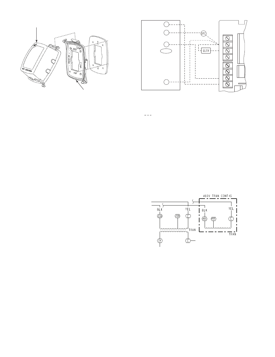
Fig. 12 — Typical Remote Thermostat Connections
CONTROL CIRCUIT WIRING — Control voltage is 24 v.
See Fig. 8 and the unit’s label diagram for field-supplied
wiring details. Route control wires through the opening in
unit’s end panel to the connection in the unit’s control box.
CONTROL TRANSFORMER WIRING (38AUZ07-14
Units)
—
On multivoltage units, check the transformer
primary wiring connections. See Fig. 13 or refer to the unit’s
label diagram.
If the unit will be operating at 208-3-60 power, remove the
black wire (BLK) from the transformer primary connection
labelled “230” and move it to the connection labelled “208”.
See Fig. 13.
Fig. 13 — Control Transformer Wiring
RECEPTACLE
NOT INCLUDED
COVER – WHILE-IN-USE
WEATHERPROOF
BASE PLATE FOR
GFCI RECEPTACLE
R
Y1
G
O/B/Y2
C
(Notes 1, 2)
(Note 3)
Note 1: Typical multi-function marking. Follow manufacturer’s configuration
instructions to select Y2.
Note 2: Y2 to economizer required on single-stage cooling units when
integrated economizer function is desired
Note 3: Connect only if thermostat requires 24-vac power source.
Field Wiring
Central
Terminal
Board
W1
Y2
Y1
R
W2
G
C
X
W1
Y2
Y1
R
W2
G
C
X
T–STAT