Carrier 38AUZ User Manual
Page 8
8
in the liquid line. Refer to the indoor unit installation
instructions for additional details.
Determine equivalent line length adjustments for path and
components and add to linear line lengths. See Tables 2 and 3;
also refer to Part 3 of the Carrier System Design Manual and
E20-II® software for design details and line sizing.
Suction line sizing – Select a tube size that produces a suction
pressure drop in range of 1.5 to 3.0°F (0.8 to 1.7°C). (Higher
pressure drops are permissible but there will be a loss in
cooling capacity due to the higher pressure drop.) Insulate the
suction line.
Liquid line sizing – For linear line lengths up to 50-ft (15 m),
select a tube size that produces a liquid pressure drop of
approximately 2°F (1.1°C). For linear line lengths greater than
50-ft (15 m), select a line size that will permit the liquid
state-point subcooling entering the indoor coil’s TXV to be a
minimum of 2°F (1.1°C).
Hot Gas Bypass – Hot gas bypass, if used, should be
introduced before the evaporator. (A bypass route that also
bypasses the evaporator circuit may lead to oil trapping in the
evaporator circuit during low load conditions and then to oil
slugging as evaporator load increases.) Model 38AUZA units
do not include a hot gas stub connection; a tee must be field-
supplied and installed in the compressor discharge line. Run a
½-in OD line between outdoor unit and evaporator coil inlet.
Install an Auxiliary Side Connector at the evaporator between
TXV and distributor (follow instructions for the side connector
part). Insulate the hot gas line.
Note that refrigerant suction piping should be insulated.
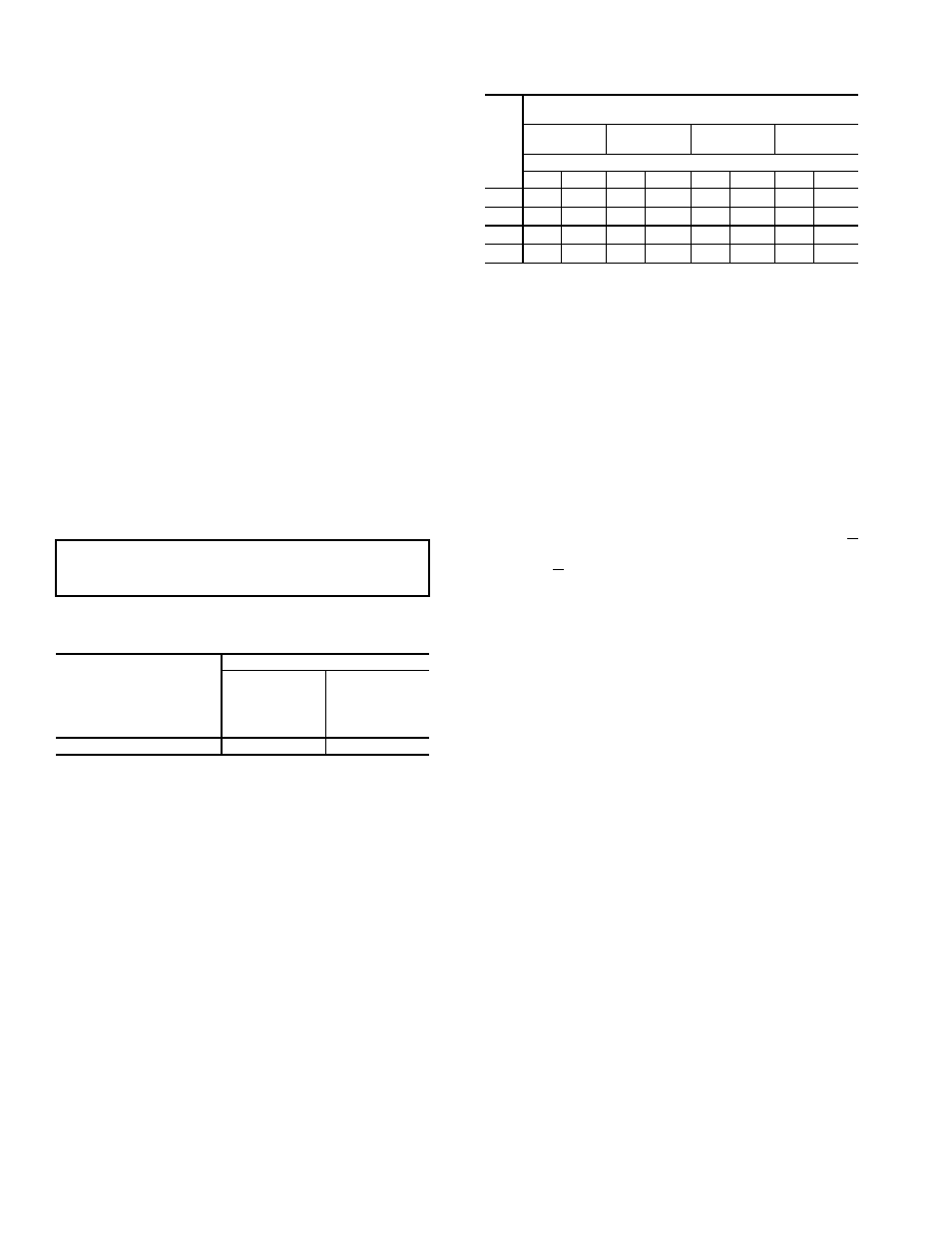
Table 2 — Liquid Line Data —
38AUZ*07-14 60 Hz Units,
Table 3 — Refrigerant Piping Sizes —
38AUZ*07-14 60 Hz Units
INSTALL FILTER DRIER(S) AND MOISTURE
INDICATOR(S) — Every unit should have a filter drier and a
liquid-moisture indicator (sight glass). Refer to Table 4. In
some applications, depending on space and convenience re-
quirements, it may be desirable to install 2 filter driers and sight
glasses. One filter drier and sight glass may be installed at A
locations in Fig. 5; or, 2 filter driers and sight glasses may be
installed at B locations.
Select the filter drier for maximum unit capacity and minimum
pressure drop. Complete the refrigerant piping from the indoor
unit to the outdoor unit before opening the liquid and suction
lines at the outdoor unit.
INSTALL LIQUID LINE SOLENOID VALVE —
SOLENOID DROP — It is recommended that a solenoid
valve be placed in the main liquid line (see Fig. 5) between the
condensing unit and the evaporator coil. Refer to Table 4. (A
liquid line solenoid valve is required when the liquid line
length exceeds 75 ft [23 m] or when the condensing unit is con-
nected to a chiller barrel in a built-up chiller system.) This
valve prevents refrigerant migration (which causes oil dilution)
to the compressor during the off cycle, at low outdoor ambient
temperatures. Wire the solenoid in parallel with the compressor
contactor coil (see Fig. 5). This means of electrical control is
referred to as solenoid drop control.
INSTALL LIQUID LINE SOLENOID VALVE (Optional)
— CAPACITY CONTROL — If 2-step cooling is desired,
place a solenoid valve in the location shown in Fig. 5.
MAKE PIPING CONNECTIONS — Piping connections at
the 38AU unit are ball valves with stub tube extensions. Do not
open the unit service valves until all interconnecting tube braz-
ing as been completed.
The stub tube connections include ¼-in SAE service fittings
with Schrader valve cores (see Fig. 6). Before making any
brazed connections to the unit service valves, remove both
Schrader valve caps and cores and save for re-installation. Con-
nect a source for nitrogen to one of these service fittings during
tube brazing to prevent the formation of copper oxides inside
the tubes at brazed joints.
When connecting the field tubing to the 38AU service valves,
wrap the valves in wet rags to prevent overheating.
IMPORTANT: For 38AUZ*07-14 applications with liquid
lift greater than 20 ft (6 m), use
5
/
8
-in. liquid line.
Maximum lift is 60 ft (18 m).
MAXIMUM
ALLOWABLE
LIQUID LIFT
ft (m)
LIQUID LINE
Maximum
Allowable
Pressure
Drop
psig (kPa)
Maximum
Allowable
Temp.
Loss
°F (°C)
60 (18)
7 (48)
2 (1)
*Inlet and outlet.
NOTE: Data shown is for units operating at 45°F (7.2°C) saturated
suction temperature and 95°F (35°C) entering air temperature. For
38AUZ*07-14 applications with liquid lift greater than 20 ft (6 m),
use
5
/
8
-in. liquid line. Maximum lift is 60 ft (18 m).
UNIT
38AU
LINEAR LENGTH OF INTERCONNECTING PIPING —
FT (m)
0-25
(0-7.5)
25-50
(7.5-15)
50-75
(15-23)
75-100
(23-30)*
Line Size (in. OD)
L
S
L
S
L
S
L
S
Z*07
3
/
8
1
1
/
8
3
/
8
1
1
/
8
3
/
8
1
1
/
8
3
/
8
1
1
/
8
Z*08
3
/
8
1
1
/
8
1
/
2
1
1
/
8
1
/
2
1
1
/
8
1
/
2
1
3
/
8
Z*12
1
/
2
1
3
/
8
1
/
2
1
3
/
8
1
/
2
1
3
/
8
1
/
2
1
3
/
8
Z*14
1
/
2
1
3
/
8
1
/
2
1
3
/
8
1
/
2
1
3
/
8
1
/
2
1
3
/
8
LEGEND
L — Liquid Line S — Suction Line
*Field-supplied suction accumulator required for pipe length 75-100 ft
(23-30 m).
NOTES:
1. Pipe sizes are based on a 2°F (1°C) saturated temperature
loss for liquid and suction lines.
2. Pipe sizes are based on the maximum linear length, shown for
each column, plus a 50% allowance for fittings.
3. Charge unit with R-410A and verify that subcooled liquid exists
at TXV by checking for a full liquid line sight glass or by calcu-
lating subcooling at TXV.