Coaxial cable requirements, Directory card replacement, Installation – Aiphone MC-D User Manual
Page 3: 1) gang box requirements
Attention! The text in this document has been recognized automatically. To view the original document, you can use the "Original mode".
COAXIAL CABLE REQUIREMENTS
Use 5C-2V or 3C-2V OR RG-59/U which must meet the following specifications;
* Both core and braided conductors must be of copper (not of copper-weldi.
* Impedance: 75 ohm.
* Ll’emiiiied chised loop DC rosislance; 7 uhin.|
* Permitted attenuation: 6 dB at 4 MHz.
* Cable sheath size should not exceed 7.4 mm (5/16")
When using 3C-2V, strip the insulation and fold back the braided conductors, as shown
to avoid shorting to core conductors.
FOLD BACK
11 mm (7/16")
3 mm (1 /8")
8.5 mm (3/8") Vl
Type; 5C-2V
Type 3C-2V
- Connect core
conductor to terminal
Connect
braided
conductors
with clamp.
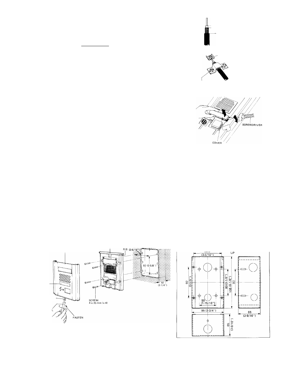
DIRECTORY CARD REPLACEMENT
The six directory cards are supplied with the MC-D unit. When re
placing the card, first remove front panel and the card cover can be
removed, using a screwdriver.
INSTALLATION
(1) Gang box requirements;
For semi-flush mounting to new and plastered wall;
MC-D can be mounted on the 3-GANG BOX as specified below;
* 3-GANG BOX, 1-5/8" DEEP, with RAISED COVER, NEMA standards.
* 3-GANG BOX, SHALLOW, The WaU Box 1/2" knockouts, NEMA standards (avahable in U.S.A.).
OR
* JIS 3-SWITCH BOX (with cover) (Model: 3SSB, to be supplied by AIPHONE).
For semi-flush mounting (in existing constructions);
To mount MC-D on existing waU or on marble wall (where no plaster is used), use Aiphone’s MCW-V box, without cover.
Cut out a hole in the waU, of W: 95 mm x H: 155 mm (W: 3-3/4" x H: 6-1/8"), securing depth of 65 mm (2-9/16").
For surface mounting;
Aiphone supplies MCW-R box, especially designed for MC-D surface-mounting. For detahs, refer to the Instructions packed
with MCW-R box.
:!0:4:T'
g
ANG
BOX imith cover)
(2) Semi-flush mounting;
main
unit
(as specified)
MCW-V dimensions;
FRONT PANEL
DIRECTORY
CARD
SPECIAL SCREW
lx 1)
1
.
2
.
3.
4.
5.
6
.
Loosen the oval head screw on bottom front panel by the provided tool.
Pull the front panel at bottom and remove from the main unit.
Connect wires on terminals on back of the main unit.
Mount the main unit on the gang box with the supplied four screws (4 mm0 x 35 mm).
Attach the front panel to the main unit inserting to the rib provided on top main unit.
Rescrew the special screw on bottom front panel by the provided tool.
- 3
-