Hydraulic lift valve adjustment – Bolens 140-990A User Manual
Page 18
Attention! The text in this document has been recognized automatically. To view the original document, you can use the "Original mode".
Caution Fan
Control Adjustment
Plate
Tear Drop Control Lever
Bolt and Nut
Loosen to Adjust
Control Slide
FIGURE 35.
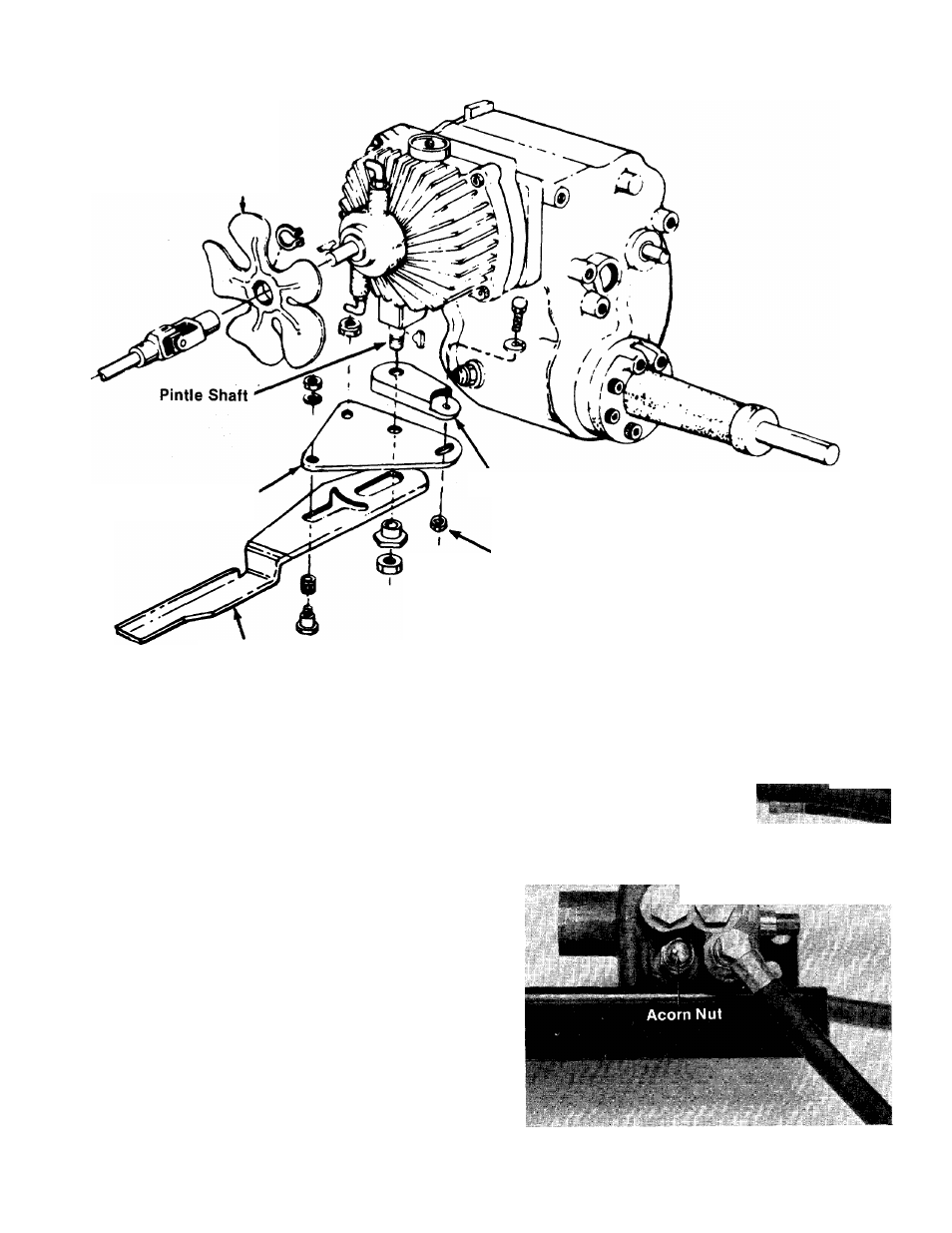
Hydraulic Lift Valve Adjustment
The valve is located under the right side of the
tractor frame directly under the hydraulic lift lever.
(See figure 14.)
The hydraulic lift valve is adjustable. Before mak
ing adjustments to the valve be sure the engine is
running at maximum speed. If the hydraulic lift
will not raise your attachments, especially the
heavier ones, you must increase the pressure.
The equipment being used should be attached to
the tractor during the adjustment.
1. Remove the acorn nut and washer. (See
figures 36 and 37.)
FIGURE 36.
18
- TMO-33603B (16 pages)
- 137-645-300 (32 pages)
- 135-668-000 (40 pages)
- 120-337-300 (22 pages)
- 113-164AA (18 pages)
- 12229 (32 pages)
- 13055 (36 pages)
- TMO-3394704 (36 pages)
- 546 (20 pages)
- HT816r (1 page)
- 111-516R000 (16 pages)
- 111-060 (4 pages)
- 111-068A (18 pages)
- 840 thru 849 (24 pages)
- 12228 (16 pages)
- Series 544 (20 pages)
- 118-620A (12 pages)
- 111-050R304 (16 pages)
- 115-500-000 (16 pages)
- 500 (12 pages)
- 340 (16 pages)
- 122-336A (24 pages)
- 506 (20 pages)
- 436 (20 pages)
- 800 (32 pages)
- 52068 - 5HP (24 pages)
- 416 (18 pages)
- 131-050A (32 pages)
- 544 (18 pages)
- BL50 (44 pages)
- 110-121-306 (4 pages)
- 112-340-300 (16 pages)
- 115-050A (8 pages)
- 13AM673G022 (24 pages)
- 112-413R352 (16 pages)
- 132-390A (32 pages)
- 120-270A (17 pages)
- BL100 (64 pages)
- 249-596-000 (12 pages)
- 120-282R000 (20 pages)
- 12226 (36 pages)
- 113-530 A (12 pages)
- 117-530-300 (16 pages)
- 114-808L401 (16 pages)
- TRANSMATIC LAWN TRACTOR 660 (32 pages)