Condensate drain, Ground level installation, Clearances – Bryant 479 D User Manual
Page 3: Ii. installing vent caps, Iii. duct connections, Iv. gas connections
Attention! The text in this document has been recognized automatically. To view the original document, you can use the "Original mode".
The mounting base should comply with local codes
and be made of noncombustible material. The recom
mended types of mounting bases for all installations
are:
a.
Precase concrete lintels.
Use three lintels run the
depth of the unit; one under the right end, one under
the left end, and one at the center of the unit.
b.
Steel beams.
Use three I-beams run the depth of
the unit; one under each end and one at the center.
c.
Concrete Slab.
A minimum thickness of four inches
is required.
Rooftop Installation
When installing the 479 on a roof or other com
bustible material, use noncombustible supports and
allow a 6 inch clearance beneath the unit’s subbase
for proper air circulation. Be sure the roof construc
tion will support the weight of the equipment. Locate
the unit above a load-bearing wall whenever possible.
Condensate Drain
The 479 is furnished with a 3/4 inch FPT drain con
nection. If the installation requires draining the con
densate away from the roof of the building, connect
tubing, pipe, hose or trough and pitch downward one
inch for every ten feet of horizontal run.
Ground Level Installation
The 479 should be placed on a concrete slab at least 4
inches thick. Level the unit on the slab and be sure
there is adequate drainage away from its base.
Clearances
The minimum clearances are 6 inches from the duct
side and 24 inches from all other sides.
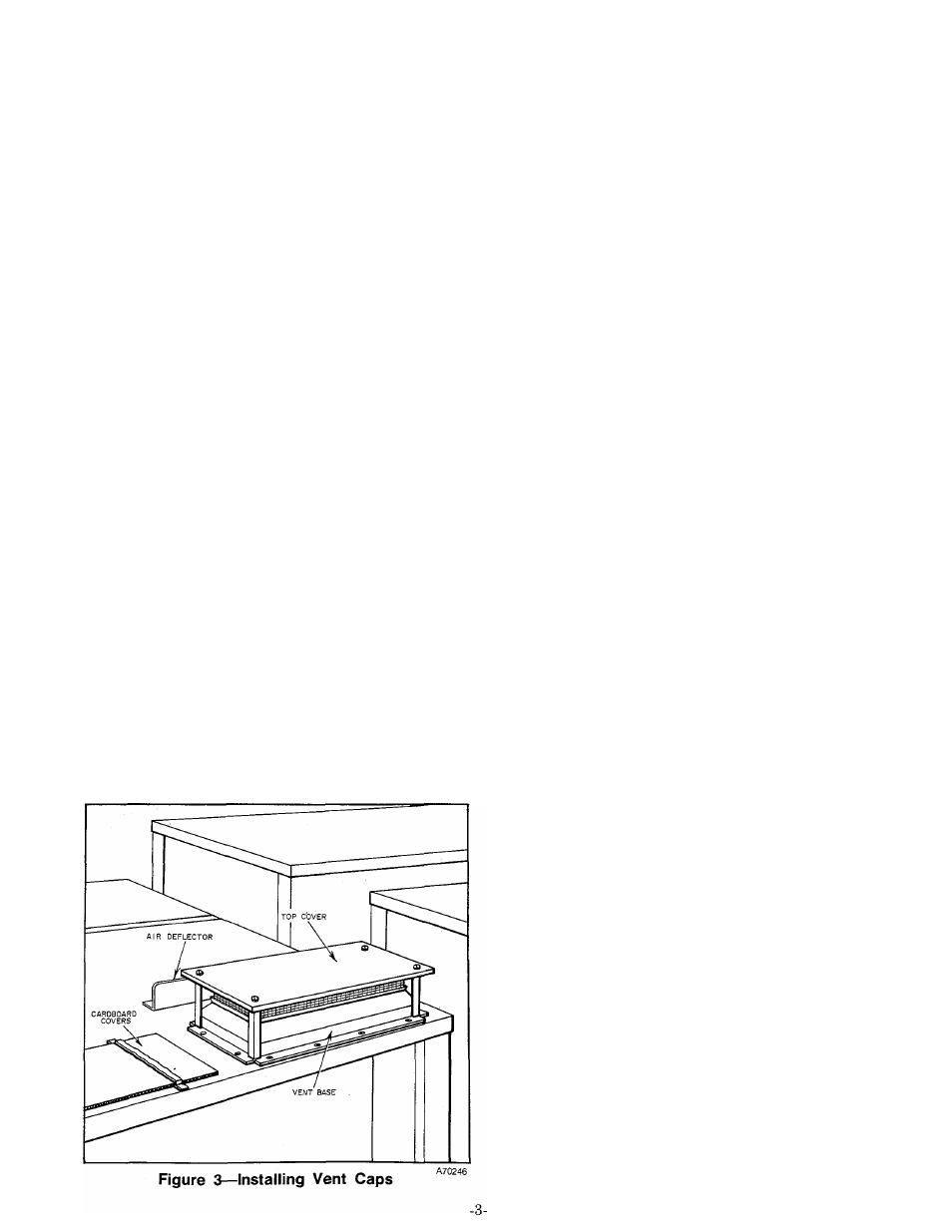
II. INSTALLING VENT CAPS
The vent cap assemblies are packaged and shipped in
the heating section coil compartment. Install the vent
cap assemblies as follows. See Figure 3.
Mounting Bases
1. Remove the cover on each of the vents on the roof
of the unit.
2. Use the FAJ5606B screws supplied with the assem
blies to fasten the base section of the vent cap assem
bly.
3. Remove the three self-tapping screws in the top
cover, located approximately 7 inches behind each
vent cap. Attach one of the air deflectors in this
location for each vent cap, using the screws removed.
III. DUCT CONNECTIONS
Before attaching the ducting to the unit, remove the
sheet metal panel that is used to protect the outlet
and return openings. The ductwork may be screwed or
bolted to the unit flange with suitable gaskets to in
sure a weathertight seal. Be sure the sheet metal
overlaps the flange on the unit.
CAUTION: Take care not to puncture the evaporator
coil when drilling the duct flange.
All duct work external of the structure must be
properly insulated and water-proofed.
All openings in the structure must be properly flashed
and vibration isolated in accordance with local codes
and good building practices. Supply and return duct
work should be provided with an approved vibration
eliminator. The vibration eliminator must be located
within the structure.
IV. GAS CONNECTIONS
The gas supply pipe for the Model 479 should be a
direct line from the gas meter or propane supply tank.
The gas supply pipe should terminate at the unit with
a tee.
The size of the gas pipe used depends upon the length
of run and allowable pressure loss established by the
utility. Never use pipe smaller than the gas connection
to the unit manifold.
The following are pertinent recommendations:
1. Avoid low spots in long runs of pipe. It is best to
grade all pipe 1/4 inch in every 15 feet to prevent
traps. All horizontal runs should grade up to risers.
2. A drip leg must be provided at any point in the line
of pipe where condensate may collect. Such drip leg or
drip legs shall be installed in locations readily ac
cessible to permit cleaning or emptying. The drip legs
should not be located where they are subject to
freezing. See Figure 4. Check local codes for size and
capacity of drip legs.
3. Three manual shutoff valves should be installed;
one valve between the gas supply pipe and heating
section, and one between each chiller and the gas sup
ply pipe.
4. A ground joint union should be installed between
the individual gas controls manifold and each manual
shutoff valve.