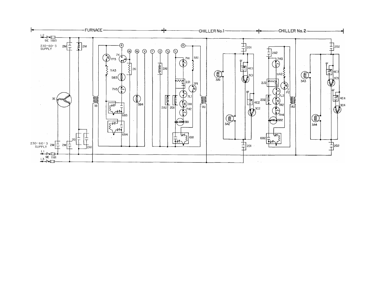
Legend, Figure 7—model 180-479 wiring diagram – Bryant 479 D User Manual
Page 11
Attention! The text in this document has been recognized automatically. To view the original document, you can use the "Original mode".
9E 1IB2
LEGEND
1A1 & 1 A2-Transformer (Cooling)
1 B-Transformer (Heating)
2A1-Blower Relay, SPST, (Cooling)
2A2-Control Relay, SPST
2D1 & 2D2-Power Relay, DPST, (Cooling)
2G-Heating Relay
2J1 & 2J2-Relay Circuit Breaker Lockout
2M-Blower Contactor, TPST
3A1 & 3A3-Solution Pump Motor
3A2 & 3A4-Water Pump Motor
3C1 Thru 3C4-Fan Motor, PSC
3E-Blower Motor
5B1 & 5B2-Gas Valve (Cooling)
5B3-Gas Valve (1st Stage) (Heating)
5B4-Gas Valve (2nd Stage) (Heating)
6B1 Thru 6B4-Reignition Pilot
7A1 & 7A2-Pressure Switch, SPST
7H1, 3, & 5-Limit Switch (High Temp Cent.)
7H2, & 4-Limit Switch (Sec. High Temp.
Manual Reset), SPST
7K-Limit Switch, Upper, SPOT
7L1 & 7L2-Ambistat (Part Load Control),
SPST
7P1 Thru 7P3-Pressure Switch,
SPST
9E-Disconnect Switch
11A1 Thru 11A3-Resistor
11B1 & 11B2-30 Amp. Fuse
11B3-50 Amp Fuse
4E1 Thru 4E4-Capacitor
Pilot Gas,
Figure 7—Model 180-479 Wiring Diagram