Actual lc-s master station terminal locations, Installation for wall mounting – Aiphone LC-5S User Manual
Page 3
Attention! The text in this document has been recognized automatically. To view the original document, you can use the "Original mode".
Begin your installation with master station no. 1. (Master stations should be designated no. 1, no. 2, no. 3, etc.
All masters included in your system should be connected and tested before beginning substation installation.) A space
is provided at the left of the all master diagram (on page 4 and 5 of this manual) to write in your color code. Note the posi
tion of the C terminal at each master station. Be sure you wire each station correctly.
After installing your second station we recommend that the power supply be connected to the + and — terminal
lines at a convenient location and that a test be made for calling and talking between each station. (If batteries are used,
insert batteries.) As each additional station is installed re-test between each station. Unplug power supply while making
wiring connections.
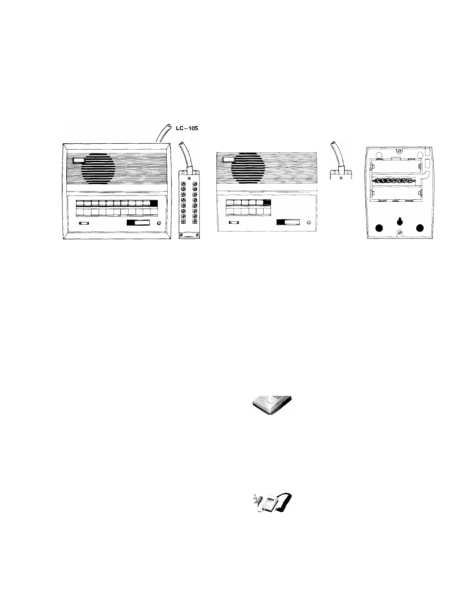
ACTUAL LC-S MASTER STATION TERMINAL LOCATIONS:
LC-5S
LC-3S
INSTALLATION FOR WALL MOUNTING.
Your LC—S system is shipped complete with screws for wall mounting. Templates are also provided for easy
proper location. Master stations and substations (except V—B) have slots, allowing the station to easily drop over the
screws protruding from the wall.
EQUIPMENT AVAILABLE FOR USE WITH YOUR LC-S LOUD SPEAKER INTERCOM SYSTEM
LC—3S: 3 call master.
LC—5S; 5 call master.
V—L: Memory call substation. .A call to
a master station from this substation will be
indicated by a sound signal and in addition
by a lamp at the master station, both of
which stay on at the master station until the
master station answers. This substation
places to and receives a call from one master.
LC—lOS: 10 call master.
V—A2: This substation places to and re
ceives calls from two masters.
II
V—A: Standard substation places to and re
ceives calls from one master.
V—B: Surface or semi-flush weather resis
tant substation. Places to and receives calls
from one master.
V—AN: Privacy substation. With the »“pri
vacy” button in the depressed position no
voice transmission from this substation is
possible, thus eliminating ‘eavesdropping’
from the master station. This substation
places to and receives a.call from one master.
•f" >
V—A4: This substation places to and re
receives calls from four masters.
PS—3: Power supply. For a system con
sisting of one master and several sub stations.
Switch must be set at 6 volt.
CS-6A: UNDERWRITERS’ LABORATO
RIES INC. LISTED power supply. For a
system consisting of one master and several
sub stations. Switch must be set at 6V.
(Available only in N. America)
PS—2S: Power supply. One required per
system. Switch must be set at 6 volt.
CS—12A: CSA Listed power supply. One
required per system. Switch must be set at
6V. (Available only in N. America)
3
-