Assembly, Instructions, Assembly instructions – Bolens 122-336-120 User Manual
Page 4
Attention! The text in this document has been recognized automatically. To view the original document, you can use the "Original mode".
A-
B-
-if
Lr
H
FIGURE 1.
ASSEMBLY
INSTRUCTIONS
NOTE
This unit is shipped WITHOUT GAS
OLINE or OIL. After assembly, see
operating section of this manual for
proper fuel and engine oil recom
mendations.
-Contents of Hardware Pack:
A (2)
B (1)
C (2)
D (2)
E (1)
F (1)
G (2)
H (1)
Hairpin Cotters
Ferrule
Curved Carriage Bolts 5/16-18 x 1.75" Long
Hand Knobs
Hex Bolt 1/4-20 X 1.50" Long
Hex Center Lock Nut i/4-20Thd.
Cable Ties
Ferrule Locking Ring
ï
\
*
11
FIGUREZ
I (7) Truss Head Bolts 3/8" Long
J (7) External Lock Washers
-K (7) Hex Nuts#10-24Thread
L (2) Cotter Pins
M (2) Tubing Connectors
1. Remove the lawn mower, loose parts, hard
ware pack and literature from the carton.
Make certain all parts and literature have been
removed before the carton is discarded.
2.
3.
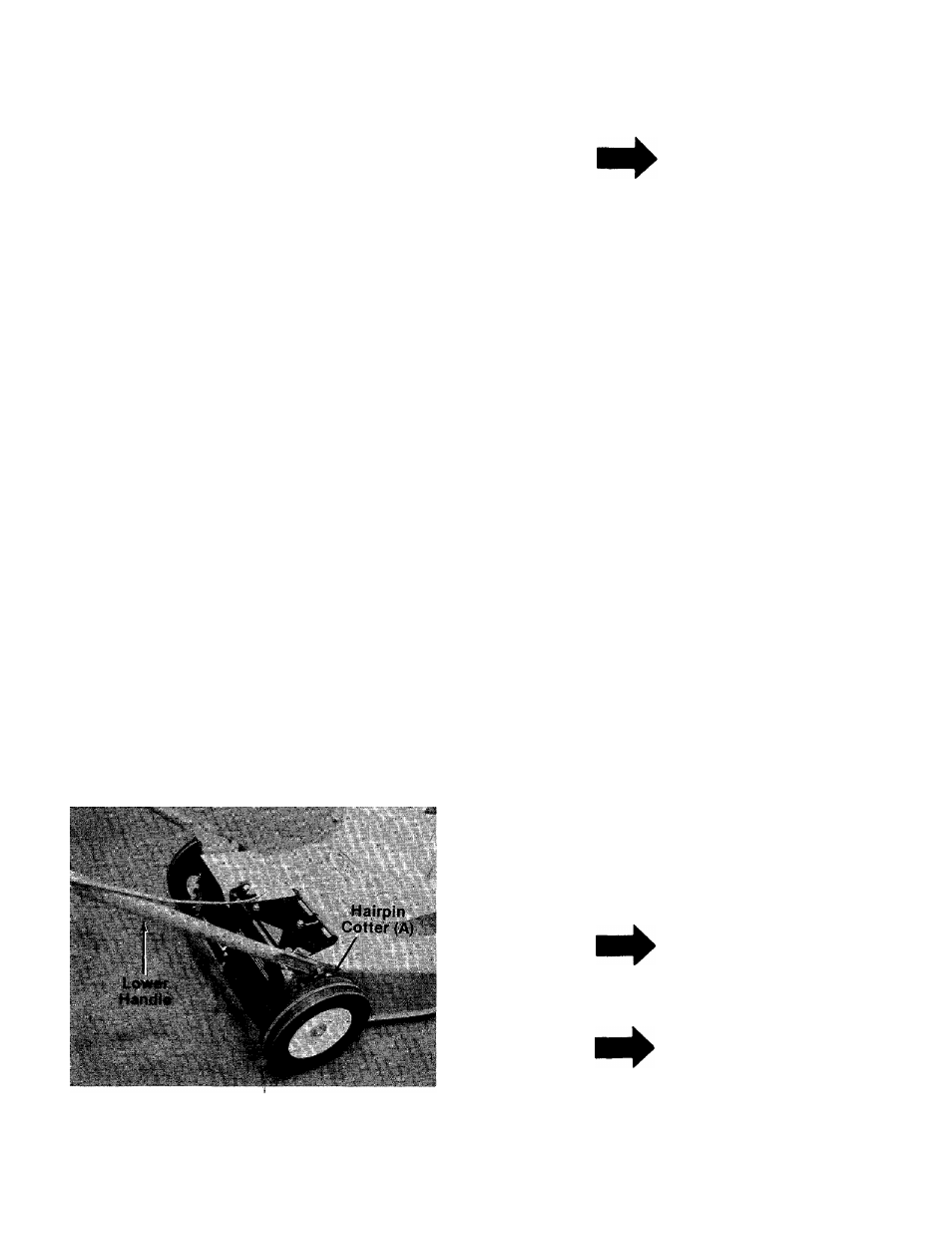
FIGURES.
Extend the throttle control which is attached
to the engine and place on the floor. Be
careful not to bend or kink control wire.
Fasten lower handle in position over weld
pins in handle mount brackets on deck. The
hole for the engagement rod in the lower han
dle must be on the left side of the unit.
Secure with hairpin cotters (A) in inner hole on
■weld pin. See figure 3.
NOTE
Reference to right hand or left hand
side of the mower is observed from
the operating position.
NOTE
It may be necessary to squeeze the
ends of the lower handle in slightly
to assure a snug fit against the han
dle brackets.