Warning, Note – Bolens 2182 User Manual
Page 11
Attention! The text in this document has been recognized automatically. To view the original document, you can use the "Original mode".
R. SINGLE PEDAL BRAKE LOCK
,WARNING
A
The hydrostatic transmission will not hold
the tractor on a hill. In a short period of time
(depending on the steepness of the hill) the
oil will drain from the transmission and allow
the tractor to roll downhill. To avoid an
accident and/or possible injury, engage the
single pedal brake lock.
Always engage the single pedal brake lock when
dismounting the tractor. To lock the brake, the turning
brake pedals must be locked together to provide brak
ing to both rear wheels. Refer to TURNING BRAKE
LOCK." Depress single brake pedal and place the sin
gle pedal brake lock in the engaged position. (See
Figure 9.) To disengage the lock, press down on the
pedal, lift the lock up and place it in the disengaged
position.
1. Single Brake Pedal
2. Single Pedal Brake Lock
S. SINGLE BRAKE PEDAL
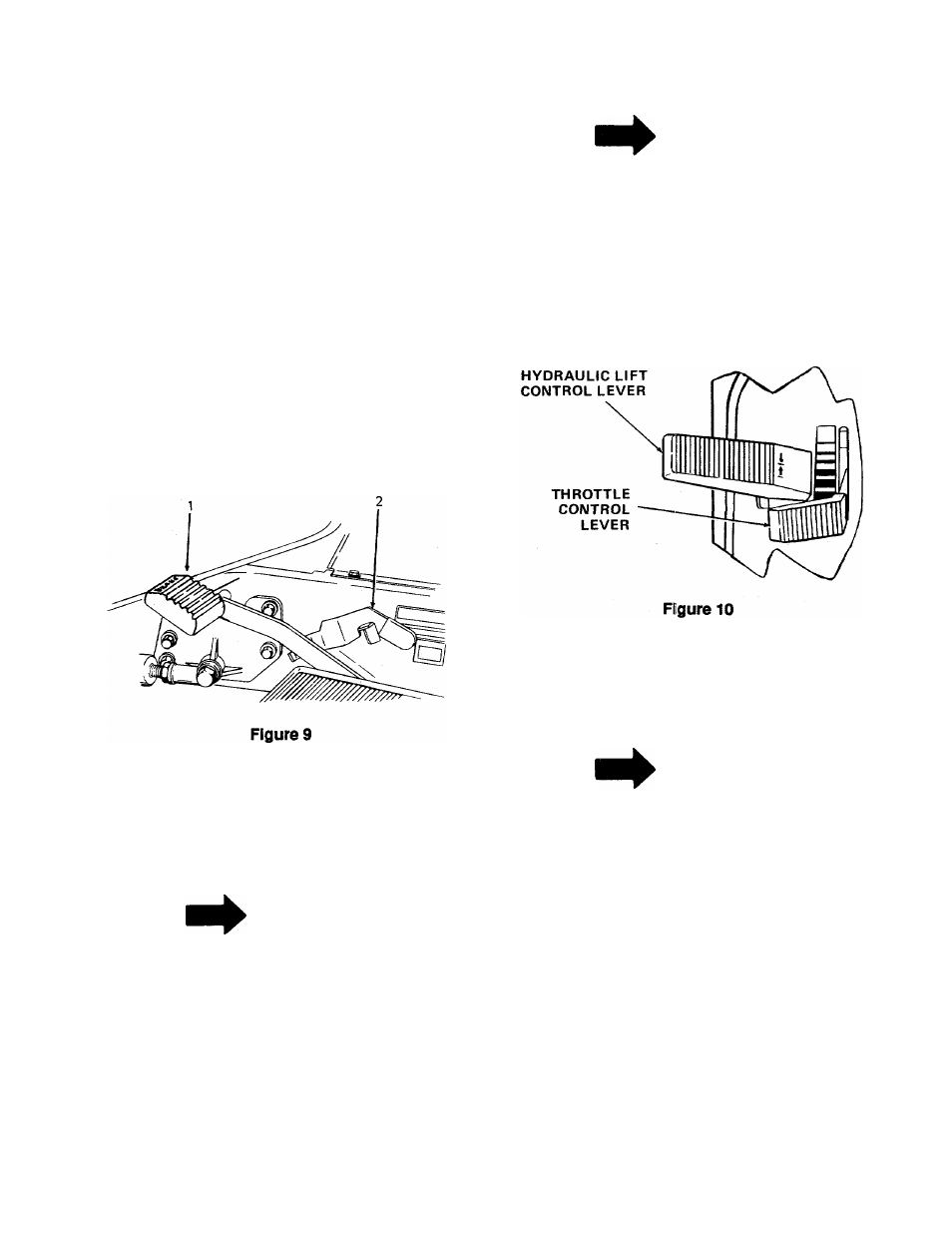
T. HYDRAULIC LIFT CONTROL LEVER
NOTE
The engine must be running in order to
operate the hydraulic lift.
The hydraulic lift control lever controls the raising and
lowering of equipment used with the tractor, if
installed. The control lever is spring loaded. To raise
the equipment, pull up on the lever. To lower the
equipment, push down on the lever. (See Figure 10.)
U. THROTTLE CONTROL LEVER
This lever controls the sipeed of the engine. When set
in a given position, it will maintain a uniform engine
speed. (See Figure 10.)
NOTE
When using power take-off operated equip
ment, best performance is achieved with the
throttle lever in the "FAST" position.
NOTE
Do not rest your foot on the single brake
pedal while driving the tractor as this would
cause the speed control lever to return to the
"N" position.
The single brake pedal must be pressed all the way
down to activate the safety starting switch. When the
single brake pedal is in the depressed position it
automaticaily moves the speed control lever to the "N"
position. (See Figure 9.)
This symtrol shows slow ("IDLE") posi
tion.
This symbol shows fast position.
V. FRONT POWER TAKE-OFF (PTO) CONTROL
SWITCH
The power take-off (PTO) control switch, which is
located on the left side of the instrument panel,
operates an electric clutch. (See Figure 3.) This elec
tric clutch controls the engagement ("ON”) or disen
gagement ("OFF") of the front PTO.
11