Table 3—burner, nozzle, anò pump pressure chart, 65 gph, Iii. fan adjustment check – Bryant 364AAN User Manual
Page 9: Vi. heating, Vii. cooling, Viii. constant blower switch, I. oil burner
Attention! The text in this document has been recognized automatically. To view the original document, you can use the "Original mode".
A U G / 2 6 / 2 0 0 8 / T U E 1 0 : 0 3
UTC TECH PUB
F A X N o . 3 1 7 2 4 0 5 6 6 2
There showJd b? e prtsspte irop of between 0.005 and 0,020
in. wc through furnace. This would set the range of the
over-fire draft between -0.01 and ~0.03 in. wc. A reading
above -0.01 in. wc (for example +0.1 in. wc) would indicate
that furnace is in an extremely high-pressure condition in
primary section- This condition may be caused by excessive
combustion air due to air baud being too wide open or.a:]ack
of flue draft (chimney effect) or some other blockage, such
as soot, in secondary section of heat exchanger.
5. The COj and stack temperature instruments ciiable you to
obtain data required to determine thermal efficiency of
furnace.
6. An oil filter should be installed as close to burner as
possible with ALL oil burners and is essential On lower
firing rate burners. We recommend the Use of a low
pressure drop oil filter such as the General Filter, lup, model
#lA‘í25A
Of
equivalent. It is .critical that oil capacity be
equivalent or greater than fuel pump gear capacity. For a
2-pipc system, this is 25 gph.
7. The oil pressure regulator is factory set to give uo^ile oil
pressures of 100 psig. The firing rate noted on nameplate
may be obtained with "standard" nozzles by adjusting pump
pressure as noted in Table 3 or on label iop fumacç,
TABLE 3—BURNER, NOZZLE, ANÒ PUMP PRESSURE
CHART
UNIT
SIZE
036070
036090
040125
046155
FIRING
RATE
GAUHR (US)
0.50
0,65
0.9Q
PUMP
PRESSURE
(PSIG)
100
100
100
1.12
104
&ECKETT OIL BURNER
Model
AFG
^ AFG
AFG
AFG
Nozzle
0,50 gph
80“ Solid
0-65 gph
70“ Hollow
0.90 gph
70“ HOMw-
1.10 gph
70° Hollow
On a new installation, air entrapped in oil line leading from
tank to nOizIe must be thoroughly purged in order to
prevent excessive after drip. The oil pump is provided with
a Special fittihg enabling'^bu to purge any air between tank
and oil pump. The proper .procedure for performiuS this
operation is as follows;
a. Place a piq^pc of dear plasticT/4-in. diameter tubing over
purge fitting on oil pump.
.
'
b. Start oil burner, then open purge fitting and aillow burner
to run until purge tube is completely free of air bubbles.
’ c. Tighten purge fitting .which will allow oil'to fun to
nosizle and fire burner.
d. If purging takes longer than „3,0 seo and no flame has
been, established, burner stops- i^ush reset button on top
of primary contro] to restart burneri
e. For detailed information On Operation of primary control,
refer to instructions included with furnace,
S. After all setup procedures mentioned above have been
completed, burner should be allowed to operate. Use an
■ inspection mirror to observe flame pattern. Any irtegulari-
ties such as burning to 1 side or pulsating flame patterns
should be corrected by changing nozzle.
III. FAN ADJUSTMENT CHECK
This furnace is equipped with ft 3-5pccd direct drive motor to
deliver a temperature rise within range specified on rating plate,
between return and supply plenums, at external duct static pressure
noted on rating plate.
Adjust fan speed so that temperature rise is within rise range
specified on rating: ¿plate. Consult wiring diagram for speed
changes on direct-drive motor.
-
„
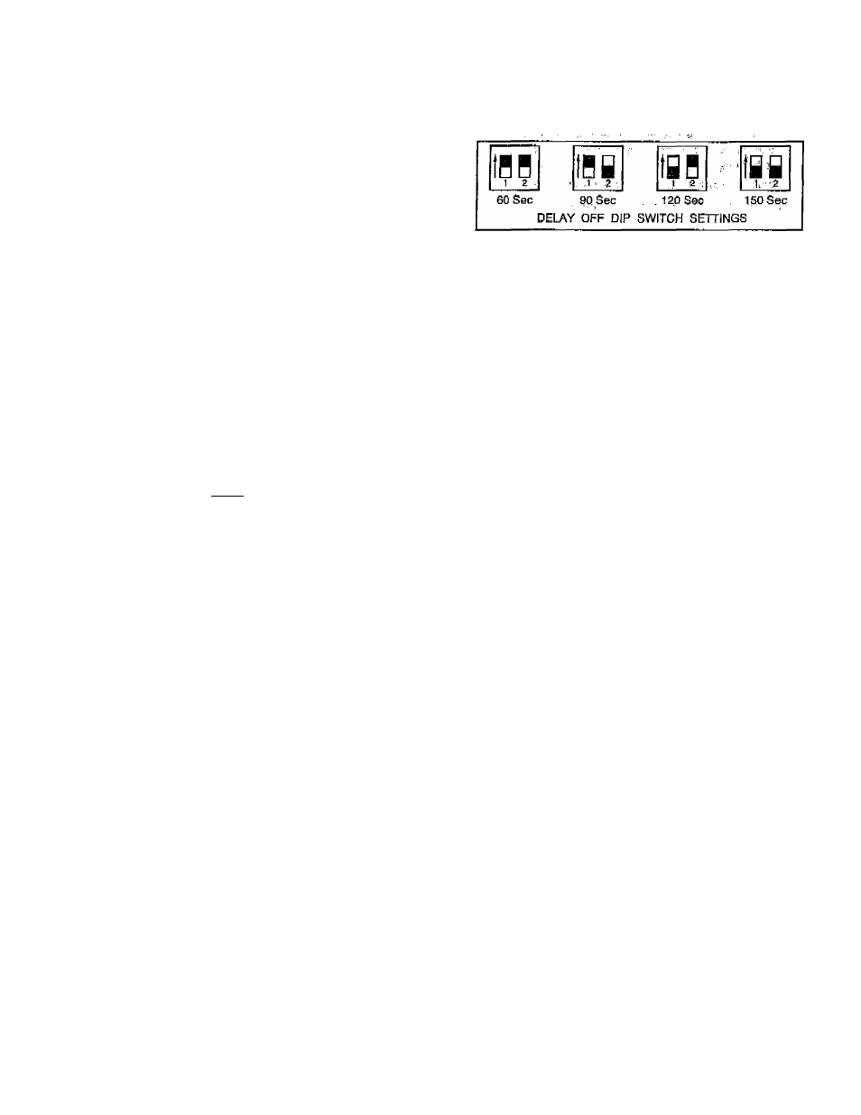
To adjust fan off time, get DIP switches on control board to obtain
desired timingV(See Fig, 12,)
■ Vf.
AS5116
IV.
Fig. 12^Fan Off Time DIP Switch Settings
LIMIT CONTROL CHECK
After furnace has been in operation
for at
least
15
minutes, restrict
rctum-air supply by blocking filters or closing return registers and
allow furnace to shut down on high limit, Th<: burner should shut
off, and main blower should continue to run.
Remove restriction, and burner should come back On iij a few
minutes, V'
V.
FOR YEAR ROUND-
air
CONDmONING
This furnace is designed for use in crinjunction-with cooling
equipment to provide year rgund air conditioning. The.blower has
been sized for both heating and cooling, however, fan motor speed
may heed to be changed to obtain ncccsshry codling airflow'.
VI.
HEATING
The blower speed is factory set to deliver required-airflow at
normal duct static pressure.
VII.
COOLING
The blower spqcd may be adjusted in the field to ¡deliver required
airflow,for cooling application^CScc Eig, 16.)
VIII.
CONSTANT BLOWER SWITCH
Thib furnace is equipped with a constant low-speed blower option.
Whenever room thermostat is not calling for heating or'cooling,
blower runs on low speed in order ;to provide air. circulation. If
constant blower option is not desired, the rocker switch-on side of
control-box .may-bc-uscdfo-turn-off-constant-speed.-
.
' MAiNtENArjce:
'7 T7 -
This furnace should .never be operated, vvithout air ,filt6r(s)..Filters
should be cleaned at least twice a year.
To avoid personal injury, make sure electrical supply power is off
before servicirig.
^
.
ALWAYS KEEP MAIN ' OIL VALVIE/TURhnED./PFF IF
BURNER IS SHUT- DOWN FOR AN EXTENi?Et? PERIOD OF
_
, ^ L>v * _. *.■
. I ' T ,
TIME,
A
WARNING;
Before performing any service functions,
unless Operations specifically require power to be on,
make sure all utilities are turned off upstream oL appli
ance. Failure to-comply with this warning wili cause a fire
hazard and/or bodily harm. <.
I. OIL BURNER
Per jodio oiling of blower motor may be necessary. Check for
instructions on inside of blower access panel.
To maintain proper performance, ’ oil burner nozzle must be
replaced once a year. Contact your dealer service technician if you
arc unsure of this procedure.
The procedure for nozzle installation and/or replacement is out
lined in oil burner instruction manual which came wi№ furnace.
For ease of maintenance, the oiling procodure for burner motor, as
Outlined in burner manual, should be performed at this time.
-
9
-