Bryant 364AAN User Manual
Page 5
Attention! The text in this document has been recognized automatically. To view the original document, you can use the "Original mode".
A U G / 2 6 / 2 0 0 8 / T U E 1 0 : 0 2
UTC TECH PUB
F A X N o , 3 1 7 2 4 0 5 6 6 2
0 0 5 / 0 1 6
О
E^CTRICAL
The appliaflce must be installed in accordance with current
ANSI/NFPA 70 National Electrical Code* CSA C22.1 Canadian
Electrical Code Part 1, and/or local codes.
The control system depends on correct polarity of power supply.
Connect HOT wire (H) and NEUTRAL wire (N) as shown in Fig.
16
.
A separate line voltage supply should be used with a fused
disconnect switch or circuit breaker between main power panel
and unit. (See Fig. 16-).
A
WARNING:
The unit cabinet must have an uninter
rupted or unbroken ground to minimiie personal injury if
an electrical fault should occur. A green ground screw is
provided in control box for this connection.
Use only copper wire for 115-y supply service to unit.
When replacing any original furnace wiring* use only:^iip5“C No.
16 AWG copper wire,.
■
'
Instructions for wiring thermostat .(field supplie'd) are packed in
thermostat box. Make thermostat connections as sjiown in Fig. 16
at 24-v terminál board 0,n control box4 ;- ■
.
■ ,
When installing optional accessories to this /Appliance, follow
manufacturer’s Installation Instructions included with accessory.
Other than wiring for thermostat, wire with a minimum of lype "T"
insulation (63'’F rise) must be used for accessories- %
á
' FILTERS
A FILTER MUST BE USEÓ Wlni THIS FURNACE! ,
An external filter rack is available as optional equipment:.with this
furnace..
Л
WARNING:
Never operate,.unit without a filter or with
filter access door removed. Failure to adhere to this
warning could lead to a haaardous condition which could
lead to equipment damage and bodily harm.
I.
KEEPING FILTERS CLEAN
As a homcownerj this is your mbit important respo'jiisibility. A
dirty .filter. LteduCes ¿f^ficiency. df 'your ,System, causes erratic
perforipance of controls, and could result,in damage to^motor or
heating equipment.
. г.
1- Inspect filters at regular intervals depending upon dirt
conditions.'pof ■'hew homes, ehcplci'fiUcrs every weeliTor 4
consecutive weeks, iln all cases, inspect filters at least every
3 to 4 weeks when sysfem is inPoiistant operation. Replace
or clean filter at least at beginning of each season (heatirig
and cooling) and thereafter as ■needed.
2. If a permanent filter is used, it^can be cleaned witl); cold
water,and soap.
;;
. ,
,
Be
Sure
that filter is thoroughly dry before installing bacic' into
furnace.
-
‘
reversing
INSTRUCTIONS FOR REAR FLUE^OPTION ,
NOTE:
These steps are only for installations where it is nfecessaiy
to have flue ccumection on
Opposite
side of furnace from biimef
and controls, Jf rear flue is not required, skip to Assembly
Instructions section.
Unit should be reversed prior to installing cabinet iri position. See
Fig, 1 for cdhiponent location,
''
'
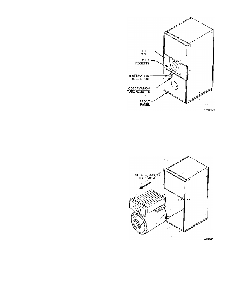
1. Remove observation tube door from front panel* taking care
not to let door spring ’’snap" hinge and pinch your fingers,
2, Remove flat rosette and gasket fram around observation
tube,-
Fig. 1"™Component Lopation..
3. Remove rosette from around fluc;oonncctof, ' . „
4. Remove front panel and flue panel from Unit,
IMPORTANT:
The heat exchanger is only secured in place by
heat exchanger ..support legs ,hopked into, brackets on blower
partition at this time. Care should be taken to adequately support
heat exchanger and prevent if from falling. Be careful not to
damage limit control.
5. Supporting heat exchanger so that it does not fail, remove
heat exchanger from cabinet by pulling it straight forward,
(See Fig. 2.)
Fig. 2—Removing Combustion Chamber and
Neat Exchanger
6. Remove cover plate/combugtion chamber assembly from
heat'exchanger drum by removing 12 parkerized screws
securing it to drum front. CAREFULLY slide combustion
chamber out of drum, taking care not to damage relatively
fragile chamber material- (See Fig, 3.)
7- Remove "blank" cover plate on rear of drum by removing
12 parkerized screws on dnim rear. Install this "blank" plate
on front (flue connector side) of drum. Ensure that gasket is
intact and all screws are secure.
- 5 ^