Ii. heat exchanger and flue pipe, Aa$iie, Blower frirward bn fsii^'^&nd but – Bryant 364AAN User Manual
Page 10: Not to.scrape or pinch, Br 'liihit wires. a
Attention! The text in this document has been recognized automatically. To view the original document, you can use the "Original mode".
A U G / 2 6 / 2 0 0 8 / T U E 1 0 : 0 4
UTC TECH PUB
F A X N o , 3 1 7 2 4 0 5 6 6 2
After rcpiacxment of nozzle, burner should be adjusted in accor
dance with Combustion Chccjt.. section of the mstnicUon,
II. HEAT EXCHANGER AND FLUE PIPE
Ordinarily, it is not necessary to clean heat e^pçl^anger or flue pipe
every year but it is necessary tp have your oil burner service
technician" check uhit bcfôrc caçh ‘heating season to determine
whether ^leaning or replacement of parts/is repujreti.
If cleaning is necessaiy, the following^Steps should be performed:
; i."Turn off all utilities upstream of fiimace.
.
2
..
Disconnect flue pipe,.
3, Remove collar on flue connection.
4. Rempye:flue'.panél,'.¡"i":
5.
Remove flue collector b6x¥fûih-sé'côhdafÿ:ihea"ïièxchangér
., , tube flange. This ^exposes inside surfaces.pfisecqn^ary tpbes
of .heatÆXchàngerVi^
r A , A ' i A
6, clean secondary iubtis and flüc pipé with a stiff^briish ^nd
vacuum c l e a n e r ! ' ■ ■ ■ ■ ' v . - ■ n^r i,;;:
'7. if only "secondary "tubes' nCd^cicà'heH^'no;'further
disassembly is required. Proceed to item IS for reassembly.
If primâr^ÿ "heat ^exchariger' ^seCtion ^'iS"'àlSo -to'^'be'''cleaned
■pr.ocecd..;tpinçxt.item:;,.
g : 'Disccinnect'‘Tim ft cbntrdl ■ wireè. ' '
^ ;
1.1.
'
l
.
i.y''/;.....,
. !
'.iir rt}''
. ..--i.,.
9. Disconnçqt oil lme..and renioye oilJiurner fr.om fernaeç,
10- Remove observation door.
.'îÆj '
,,
; 11,'Remoye„collar'iOn;0b5crv,^tionfubc. ■ .ij .
.
'
12. Remove front panel. Care must-be takeji('-not tb'bbnd Or
damage 'limit control.
' 'i
■
13. Looscri''to-'hand tightness "the
'3
nütsdabeled' f'A" in Fig;'i3,
Remove screws labeled ""B" in Fig, 3, Slide combustion
chamber forward put.of heat exchangeri,Be*careful not .to
bqmp, .combustion chamber as it become^ brittle^ ^^Çer
A ' having been fired.
..............
■ 14. Use.-a.stiff brush and vacuum iC)eaner/tO 'dean-,inside^'bf
primary^drum:,.
-.r,. ..^
■■
■. :ivt.v. ■■■i.-. '
..
A
CAUTION:
Never-use incendiary type cleaners
(smoke
sticks) for cleaniiigT‘ A
i .
1^. Befbre reáSsemtíiyríisaTexcEánger^
ber sJjOuIi^.be m^pCcted to deterinine ,if;iqp^
required .;!“^er ^lea'mng,,piace^'dp'n;l(bus
'■ ' ^ into'primary drum'and secure witli''''B"'SCrews';'Bnsuriprth^^
cover plate gasket is in place.before tightening screws:' Cái¿
'"■■ ■ müít be taken"'nüt'td'’aaroagéi:dfflbii';^fjdh":c’j^iiji[íbí^^
i.f: ■■ ,.r,
yi
.-I..' ■
16. Tighten'"A"-nuts to!30 lb-ip. of torque,(firm^,butj]ipt Overly
..
flghO-.i,.--.
•••■>
■
.■ :n;.'
(;■ ■
mi
ciiif ■ ■
17. Replace front panel, bbservatiOri^tube collar^ óbseryation
door, Um.U .wiring, and oilbiirner. ■ ■ -
.
IS. Replace collector box on secondary tube flange, ensuring
proper placement of gasket. IF GASKÍET
t
IS^DAMACED
IN ANY WAY, IT SHOULD BE REPLACE,D! Tighten
screws'fü'30-lb-in. Of torque.’'
■■
.
■
-'j.
■
f.;-'
'I'
.■ '.
19. Replace flue panel and flue COUaL^ ■
20. Reconnect flue pipe, and :oil,pipéis) if removed;; Í ■
21. Readjust burner for proper operátíbií. Check limit operation
as outlined in this manual,
lU. pLÓWEíi RfeMpVAL
To remove (blower from furnace;-
NOTE:
All directions are given as though fiimacc were installed
in downflow position. For either horizontal position, "left" and
"right" become "up" and "down" depending on position in which
furnace is installed. /
1, Turn off all utilities upstream of furnace.
2, Remove control box cover and disconnect black, red, blue,
and
White
blower wires from blower control
board
and
constant blower rocker switch. (See. -Fig. 10.) Disconnect
2-pin harness connector for auxiliary limit wires.
3.
Remove screws securing blower access panel and rotate
panel (with control box attached) down and out of way of
blower compartment. B,e careful pot to scrape or pinch
blower anid auxiliary limit wires ps they pull through wiring
hole in panel.
7j ,,
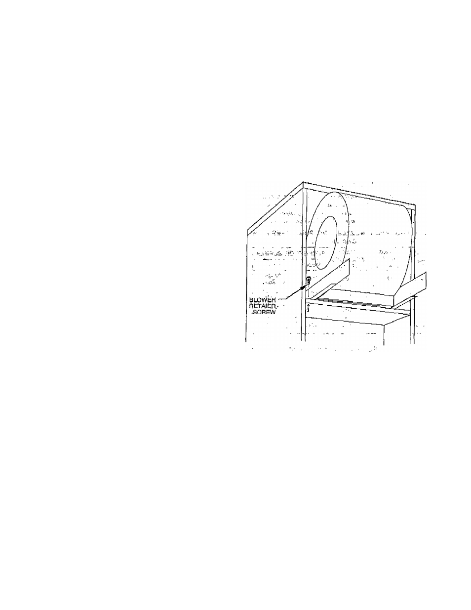
4. Remove blower retaining screw located at front of left
blower leg. (See Fig. 13.) '■
Aa$iie
Fig.
13-^Blower Rfitalnlng Screw
5- Slide
Blower frirward bn fSii^'^&nd but,
Of unit: Cafe must be
taken
not to.scrape or pinch
motof
br 'liihit wires.
A
CAUTION:
Be sure blower ?Js : adequately supported
when sliding opt pf mq,unring rails,iespccially ioihorizon-
tal posiflon,..jn ofdcr tp .pre^^^ dropping blower and
injuring yourself or damaging blower!
t::-
■6, Reverse items 1 thrblighiS to
r^ihStdR blOwCr..
Refer to Fig.
10 and. wiring diagram ^(Figi ‘16) -of this instruction, or
diagram located on inside- of blower ¡access panel to
properly rewir^.unit-
f
- 1 0 -