Bryant 364AAN User Manual
Page 7
Attention! The text in this document has been recognized automatically. To view the original document, you can use the "Original mode".
A U G / 2 6 / 2 0 0 8 / T U E 1 0 : 0 3
UTC TECH PUB
F A X N o , 3 1 7 2 4 0 5 6 6 2
0 0 7 / 0 1 6
o
ASSEMBLY INSTRUCTIONS
It is easier to install furnace if cabinet assembly (shipped in carton
■ 1 of 2) is placed into positionj ductwork connected, and THEN
control box/burn,er assembly (shipped in carton
2 of 2)
is mounted
to cabinet. Electrical^ thermostat^ and oil line connections can then
be made to completed unit.
To attach control box/burner assembly to cabinet:
1. Carefully unpack carton
2
containing prewired control
box/burncr assemb.ly .and hardware bag.
2. Remove 3 burner mounting nuts securing shipping plate on
front of furnace cabinet at burner mounting flange. Remove
and discard shipping plate. When furnace is in installed
position^ burner mounting studs should be in the 12, 3, and
9 o’clock positions, leaving bottom hole empty.
a. If furnace is being installed in downflow position, studs
are in correct .position wjie^ ,shipped from factory, ‘
. b. ff furnaceJs beingJnstallcd in horizontal position, it is
necessary to remove stud that ris mow in .6 .o^dlock
posirioti and reposition it so thaFstuds are in l2, 3', and
9 o’clock positions. It may be necessary to use Z of the
burner mpunting'iiuts as ''jsrrr"> puts pn. stud in order to
provide a means of using a‘wrench to remove,a tight
stud.
1.'
3. If furnace is installed in horizontal left airflow positíoii, it is
necessary to relocate burner wiring conduit from'ii^t side
of burner to left side as follows: (See Eig. S.) ^ > i-.-.,
a. Release clip(s) securing ignition control ^on top of burner
and swing control open to gain access to wiring com
partment inside burner.
b. Disconnect wire nuts on .black, white, and orange, wires
inside burner.
c. Remove conduit nut securing conduit to right side of
burner and detach conduit and .wires from .burner/hous-
ing.
.
d. Reipovc hole plug from left side of burner housing and
install it in hole on right side (where :;Condujt was
removed).
... ^
,
e. Feed conduifand ¡wires through-(eft^side hofe and secure
with conduifnufremoved imlteirij c'.^ ■/;
f. Reconnect blacki white, and orange wires inside burner
using'wire nuts removed in item 'b.
Close anB secure ignition control.
f'f-V.,
' 'i.H| 1'.'
4. Carefully'install burner onto burner mounting,studs, ¡ensur
ing that mounting flange ¡gasket is jpositioned between
. flange on .burner .and fronf pf furnace.. Secure, .burner ¡in
position with 3 burner mounting.y^ashers,and.iiuts removed
in item 2.
.if;.
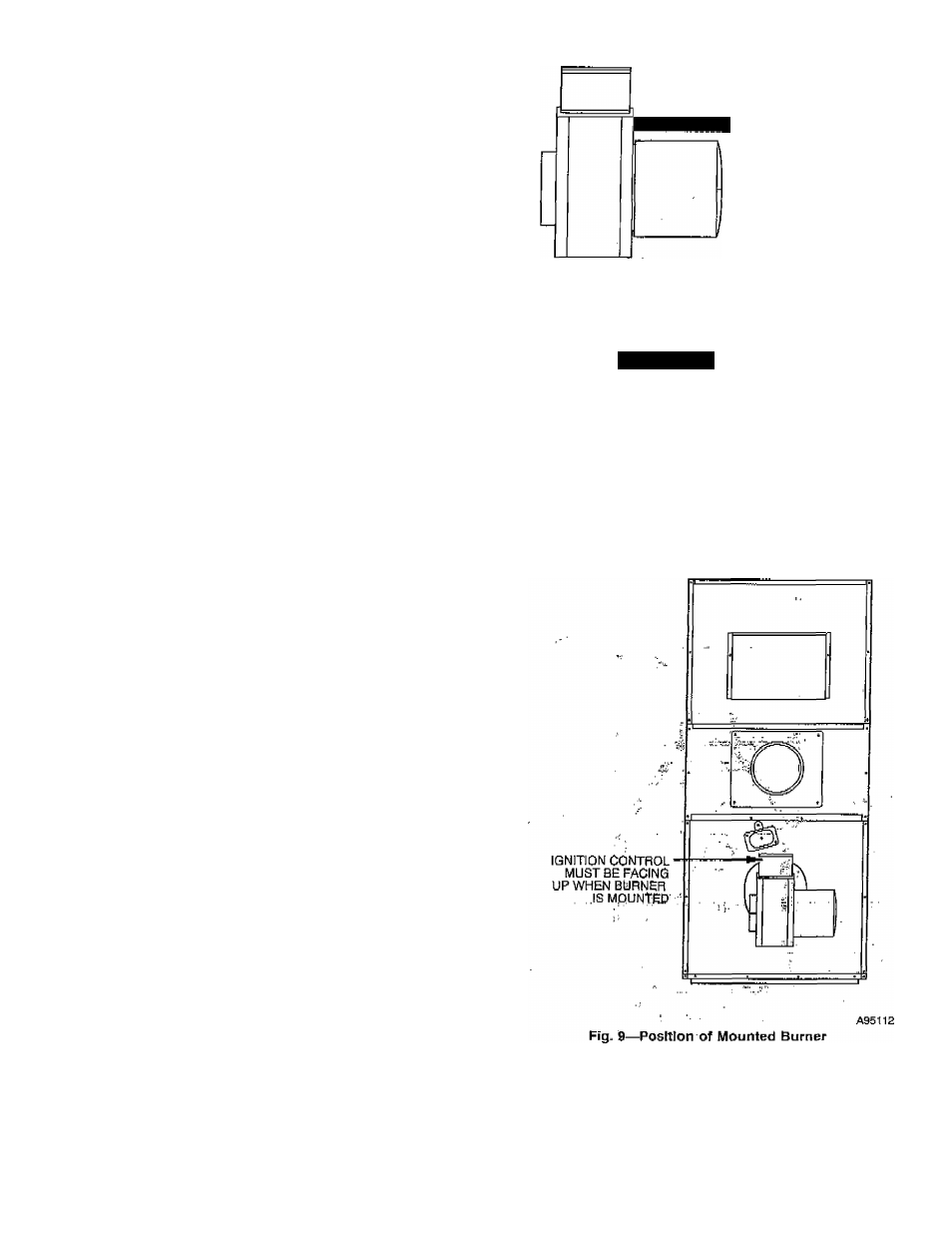
IMPORTANT: The burner must álwayS’bfe^jnstdlled in upright
position with ignition control on top, (Sec Fig. 9i)^......
5'- Attacft bontfol bok to b l o y i ' C T ' a b é M s S
sTieet 'métál'''Screws ‘froin ''hárdw'ain:'''t7'¿g''in' carton '2. The
vyirés exteh'diug .frOm'biower access párífcT.muk be routed
through large ho)c)n back of control bóxj taklng ¿aré not to
gcrapt o'rjpiiich insulation on wires.'The wires''¿hotild be
connected to1:he 2-pin harness conhéctor ánd aflfíropriate
terminals on fan control board. (See Fig.
10
arid
Í6-)
6. Attach the 2 limit switch , wires to terminals of limit switch
located on lower portion of front panel. After attaching
wires, secure limit cover to front panel using 2 No. B sheet
.metal screws from hardware bag in carton 2, (See Fig. 11.)
iiimiiiiiiiinm
CONDUIT LOCATION
FOR DOWNFLOW
AND HORIZONTAL-L^FT
(AS SHIPPED)
llllllllllllllllllj
CONDUIT LOCATION
FOR HORIZONTAL-RIGHT
{AFTER RELOCATING)
ASSÍ11
Fig. 8—Burner Wiring Conduit Location for
Horizontal Applications
(Downflow Orientation Shown)
- 7 -