Fig, 3—removing combustion chamber – Bryant 364AAN User Manual
Page 6
Attention! The text in this document has been recognized automatically. To view the original document, you can use the "Original mode".
A П П G / 2 6 / 2 0 0 8 / T U E 1 0 : 0 2
UTC TECH PUB
) . 3 1 7 2 4 0 5 6 6 2
P ,
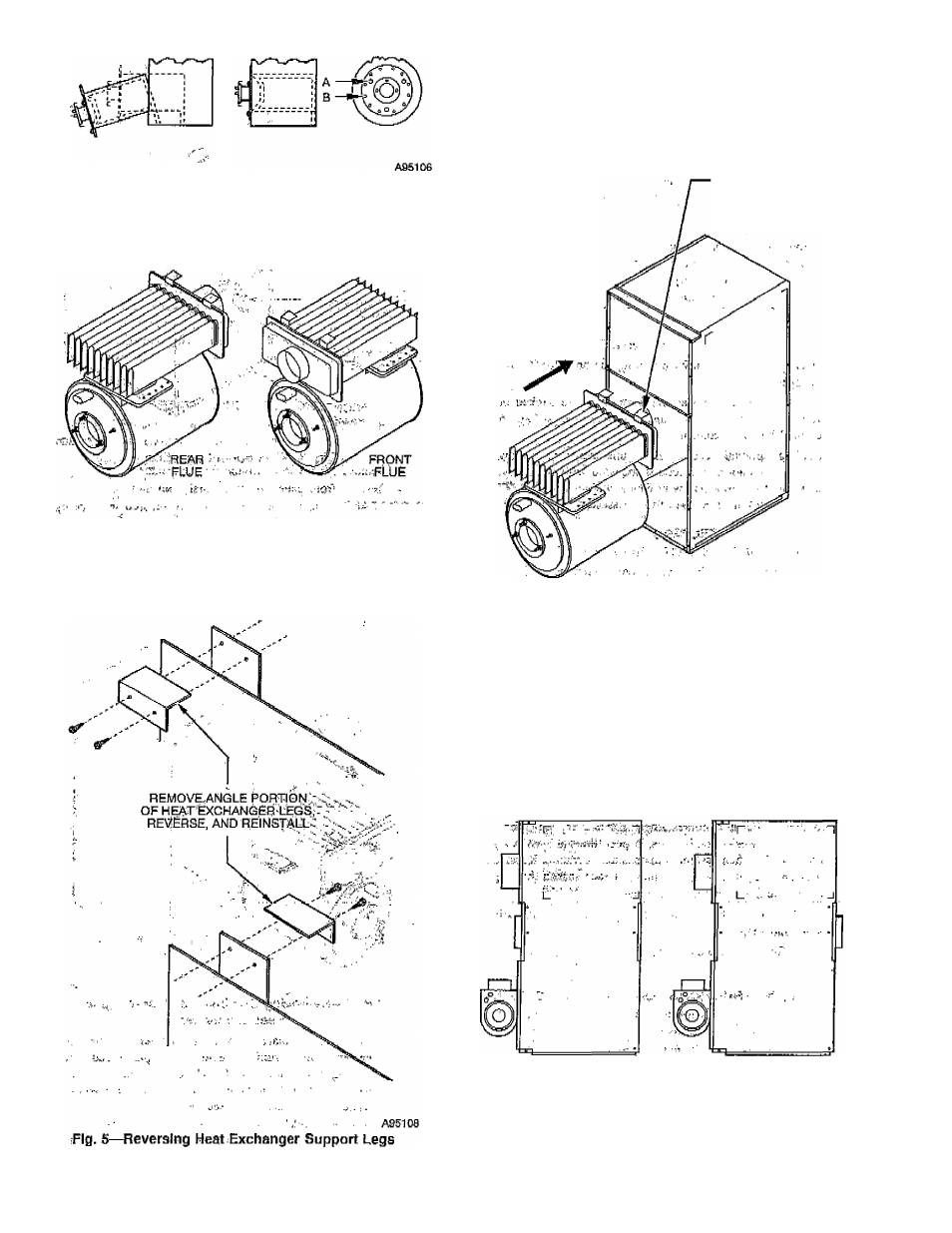
Fig, 3—Removing Combustion Chamber
8. Install cover platc/combustion chamber assembly (removed
in item 6) into rear opening of drum, taking care not to
dnm&ge chamber, cin^unng gasket is Jn-place, and verifying
that screws are ialEseeurely tightened. (See Fig. 4.)
- 'Ags'fci?
Fig. "4—Front/R^r Flue Üflehtatibhs
9.
Remove
2
screws that attach angle portion of heat eX“
changer legs to straight portion, rotate angle portion so that
they point thti opposite direction, and reattach to straight
.portion,>using.priginal screws. (See Fig. 5.)
11. Turn heat exchanger so that flue connector is toward rear of
unit and reinstall in cabinet. The heat exchanger support
legs will now engage in hangers at rear of blower partition
instead of hangers at front. The fine connector should
, protrude through opening in flue panel on rear of unit with
burner mounting flange still at front of unit. (See Fig. 6.)
HOOK SUPPORT u
LEGS UNDER,
CLIPS ON REAR
OF BLOWER PANEL
INSTALL BY
SLIDING BACK
A951Û9
Fig. 6™ReinstalMng Combustion Chamber and
'
■ i' Héât Exchanger "
12. Reinstall frOni pà^erîfemdv^^
4) and install rear
ccoterT?ancl,(rcmQyc.d îh.ithiii..liQ whdrfeZfliic panel origi
nally was. BE CAREFUL NOT TO DAMAGE LIMIT
CONTROL.
13. Replacp. rosette op ^i^.C!C|nncctpr (now at rear of furnace),
observaMon tube^ rosette M
door. ■
14. ;;Froceed with'lnstàllîng futhaçeicabinetTand. mounting oil
bumer.:and controls.
.■
FRONT FLUE
(AS SHIPPED)
. REAR FLUE
(AFTER REVERSAL)
A95110
10. RentOve rear center panel from cabinet and replace it with
flue panel removed in item 4.
Fig, 7—Component
Location Before and After
Flue l^eversal
^ 6 -