Bryant PAYNE 619C User Manual
Page 9
Attention! The text in this document has been recognized automatically. To view the original document, you can use the "Original mode".
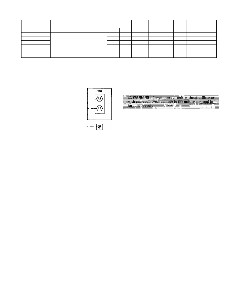
Table 5 — Electrical Data
INDOOR UNIT
V-PH
OPERATIONAL
VOLTAGE*
FAN
WATTS
ELECTRIC
HEATER
kW AT 240 V
MCA
MAX FUSE OR
HACR TYPE
CKT BKR AMPS
Max
Min
LRA
FLA
619CNX0240E0
208/230-1-60
187
253
07
0.5
92
-
1 0
15
619CNX0360E0
20
1.3
160
-
20
15
619CNX0480E0
3.7
1.0
396
—
1.8
15
619CNX0240W0
07
0.5
2092
2
11.5
20
619CNX0360W0
20
1.3
3160
3
17.9
35
619CNX0480W0
37
1.0
4396
4
22.9
40
LEGEND
FLA
— Full Load Amps
HACR — Heating, Air Conditioning, Refrigeration
LRA
— Locked Rotor Amps
MCA — Minimum Circuit Amps per NEC Section 430-24
NEC
— National Electrical Code
‘Permissible limits of the voltage range at which unit will operate
satisfactorily.
208/230 VOLT
1-PHASE
CONNECTION
TO INDOOR
DISCONNECT
<
START-UP
EQUIPMENT
GROUND
Fig. 16 — Line Power Connections
VIII. CONNECTIONS TO OUTDOOR UNIT
A. Cooling Only Systems
The following connections must be made to the 700C unit for
it to operate as a system with the indoor unit:
1. A thermistor connection cord with a lead length of 35 ft
is shipped with the 619C unit. Run the connection cord
from the condensing unit to the low-voltage terminal strip
on the control board of the fan coil unit. The stripped
end of the connection cord goes to the fan coil end. Use
care to route the wires so that they will not be dam
aged, and do not run them near power wires. Connect
the orange wires to terminals D1 and D2 on the control
board.
2. Route 2 wires of 18-gage thermostat cable between the
low-voltage terminal block of the fan coil and the 700C
unit. Connect the wires Y to blue wire going to high-
pressure switch, and R to R on the low-voltage
transformer.
B. Heat Pump Systems
The following connections must be made to the 705C unit for
it to operate as a system with the indoor unit:
1. A thermistor cord with a lead length of 35 ft is shipped
with the 619C unit. Run this cable from the heat pump
to the low-voltage terminal strip on the control board on
the fan coil unit. Use care to route the wires so that they
will not be damaged, and do not run them near power
wires. Connect the orange wires to terminals D1 and D2
on the terminal strip, and the blue wires to terminals
A1 and A2 on the terminal strip.
2. Route 4 wires of 18-gage thermostat cable between the
low-voltage terminal block of the fan coil and the 705C
unit low-voltage terminal block. Connect Y to Y, O to O,
G to G, and C to C with the wires.
The following checks should be made before system start-up.
Refer to 700C or 705C installation, start-up and service in
structions for system start-up instructions and refrigerant
charging methods.
1. Check condensate drainage system.
a. Remove grille and frame from the unit.
b. On the opposite side of the drain connection, insert a
water bottle up into the fan coil unit and fill drain
pan. Refer to Fig. 18. Water must flow regularly; if
not, check the pipe slope or inspect for any pipe
restrictions.
2. Make sure that all wiring connections are correct and
that they are tight.
3. Check that all barriers, covers, and panels are in place.
Ensure that the filters and return-air grilles have been
installed and that the discharge louvers are positioned
correctly.
I. AFTER EXTENDED SHUTDOWN
If the system has been turned off for more than 12 hours,
turn on the indoor and outdoor unit disconnect switches to
supply power to the system for 12 hours BEFORE starting
the system.
II. SEASONAL CHANGEOVERS
When changing heat pump system from cooling to heating or
heating to cooling, or before starting cooling only system af
ter it has been out of use for the winter season, the following
steps must be performed.
BEFORE starting the system:
1. Inspect and clean the outdoor unit, particularly the coil.
2. Clean or replace the air filters in the indoor unit.
3. Clean the indoor unit drain pan and drain pipe, and re
move any obstructions.
4. Turn on indoor and outdoor unit disconnect switches to
supply power to the system 12 hours before starting the
system.
-
9
-