Bryant PAYNE 619C User Manual
Page 5
Attention! The text in this document has been recognized automatically. To view the original document, you can use the "Original mode".
(SLIDE INSERT)
REINFORCING
BAR«
I WOODEN
HANGING I BRACE
BOLT
REAM
(EDGE
SHARP
“
INSERT)
"‘
embedded
BOLT
(EMBEDDED BOLT
OF PIPING)
WOODEN STRUCTURE
^HANGER BOLT
IL à
NEWLY BUILT CONCRETE SLAB
^EXPANSION
ANCHOR
METAL STRUCTURE
PREVIOUSLY
BUILT CONCRETE SLAB
Fig. 4 - 619C Unit-Mounting Methods
(Hardware is Fieid Suppiied)
INDOOR UNIT
BOLT
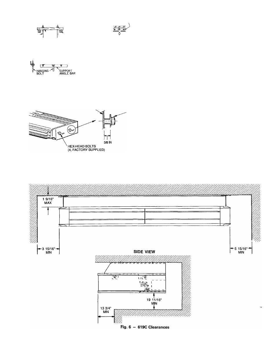
Fig. 5 - instaliing Hex-Head Mounting Boits
in 619C Unit
e. On heat pump installations check for factory-installed
piston in service valve. If not already installed, in
stall piston in the metering device located in the ser
vice valve on the outdoor unit (Fig. 13). Make sure
Teflon seal on the piston faces toward the outdoor unit.
Use Table 4 to determine required piston size for the
system being installed.
f Refer to 700C and 705C installation, start-up and ser
vice instructions for additional information.
g. Install a liquid line filter drier near the outdoor unit.
On heat pump systems, a bi-flow filter drier must be
used.
3. Insulate and caulk wall openings to reduce air infiltra
tion and refrigerant pipe vibrations on structure.
4. Evacuate piping, if necessary. If either refrigerant pip
ing or the indoor coil is exposed to atmospheric condi
tions for longer than 5 minutes, it must be evacuated to
1000 microns to eliminate contamination and moisture
in the system.
V. CONNECT CONDENSATE DRAIN LINE
Observe all local sanitary codes when installing condensate
drains. Refer to Fig. 3 and 14 for drain hose connection from
indoor unit.
1. Use hard polyvinyl chloride (PVC) pipe material with
nominal ID of 3/4 in. to connect at drain line. Use pipe
insulation 1/4-in. thick, such as Armaflex insulation, on
exposed piping inside the conditioned space.
FRONT VIEW
-
5
-