Bryant PAYNE 619C User Manual
Page 8
Attention! The text in this document has been recognized automatically. To view the original document, you can use the "Original mode".
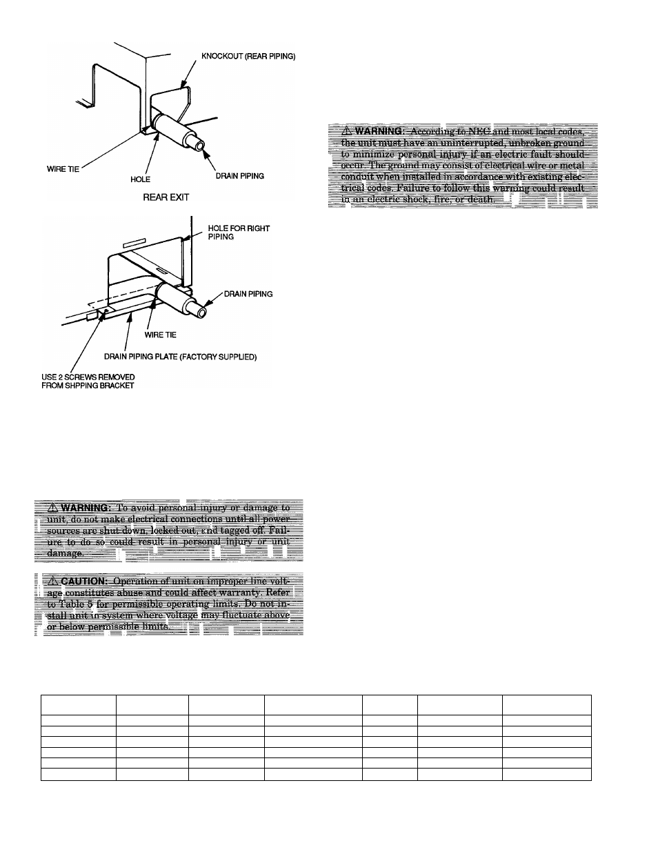
RIGHT-HAND EXIT
Fig. 15 — Routing Drain Piping
VI. MAKE ELECTRICAL CONNECTIONS
Be sure field wiring complies with local building codes and
NEC, and unit voltage is within limits shown in Table 5.
Contact local power company for correction of improper line
voltage.
NOTE;
Install branch circuit disconnect of adequate size to
handle unit starting current per NEC. Locate disconnect within
sight from and readily accessible from unit, per Section 440-14
of NEC. Some codes allow indoor unit to share disconnect with
outdoor unit if disconnect can be locked; check local code be
fore installing in this manner.
1. Route ground and power wires.
NOTE:
Use copper wire only between disconnect switch and
unit.
2. Route line power leads (see Fig. 16) from indoor discon
nect to the fan coil unit. Place wire through hole on the
control box (Fig. 17). Connect wire to high voltage ter
minal board (TB-1) and ground screw. When routing the
wire in the unit, use care to keep the wire away from
refrigerant and condensate piping and any sharp edges.
Units are factory wired for 230 V to 24-V transformer
operation. For 208 V to 24-V operation, interchange blue
(208 V) and red (230 V) wires. Cap unused wires with
wire nuts.
VII. INSTALL CONTROL
The 619C unit is equipped with a microprocessor control which
operates the system. This control is located in the control box
of the fan coil, with thermistors located in the fan coil inlet
and discharge, on the indoor coil, on the outdoor coil, and in
the outdoor-air inlet (heat pump systems only). The ther
mistors monitor system operation and control the operating
mode. To change settings or modes of operation, a wired re
mote controller is supplied.
The factory-preset DIP switches on the 619C control board
set the operation of the unit cooling only or for heat pump
operation. Be sure the switches are set correctly. See wiring
diagram on page 16 or 17, and also the control, service, and
troubleshooting guide (available from your distributor) for more
information.
A. Wired Remote Controller
The wired controller is directly connected to the unit by the
plug connection provided. Standard cable length is 15 ft, but
the cable can be any length up to 200 ft.
Determine where the best location is to mount the controller.
Since the controller is not used to sense the temperature of
the room, locate the controller in a convenient place that is
easily accessible to the user.
The cable can be surface mounted or may be run over ceil
ings and through walls. Follow local codes when installing
low voltage wires.
To install remote controller, see separate remote controller
installation instructions.
Table 4 — Required Piston Size for Check-Flo-Rater™ Metering Device
OUTDOOR UNIT
INDOOR UNIT
INDOOR PISTON
INDOOR PISTON TYPE
OUTDOOR
PISTON
OUTDOOR PISTON
TYPE
REQUIRED SYSTEM
CHARGE * (lb)
700CNX024
619CNX0240E0
55
B
-
A
68
700CNX036
619CNX0360E0
65
B
-
A
6.8
700CNX048
619CNX0480E0
84
B
-
A
too
705CNX024
619CNX0240WO
-
B
~
A
-
705CNX036
619CNX0360W0
-
B
-
A
-
705CNX048
619CNX0480W0
-
B
-
A
-
LEGEND
B - Chatleff
'Charge amount is determined with 25 ft. of iine
-
8
-