Bryant PAYNE 619C User Manual
Page 6
Attention! The text in this document has been recognized automatically. To view the original document, you can use the "Original mode".
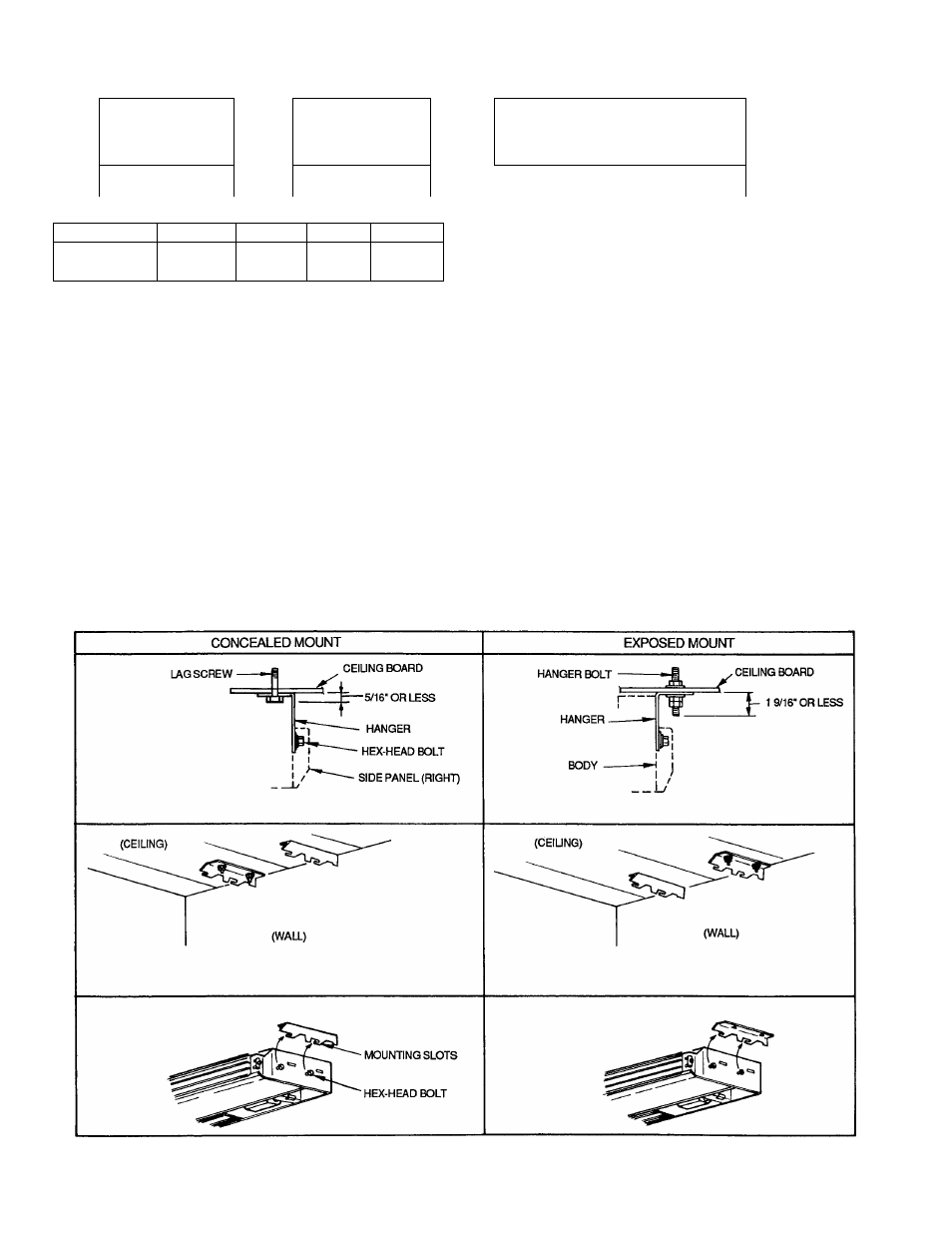
CONCEALED MOUNTING
HOLE FOR HANGING BOLT
4 -1/2"
X
1" SLOTS
EXPOSED MOUNTING
HOLE FOR HANGING BOLT
4
-
1/2”
X
1" SLOTS
SIDE VIEW OF RIGHT-
SIDE PANEL
T
3 5/8"
i
ri-|='C io
T
:«i' 1 u-fi
IV" !
21_____ 1______ IQ
23 5/8”
1
IT
r
-................................
1
1
rtrr 1
iliC - -------------
B________ >1
1--------------- A
1--------------- D----------------- 1
h--------------- A---------------- -
Fio. 9 — Removina Rear Knockout
CUTTHESUT
PORTION IN REAR
OF PANEL WITH
A SAW OR CUTTER
KNIFE
DIMENSIONS (in.)
UNIT 619C
A
B
C
D
024
50'5/i6
46
6'/8
49V
b
036
58'3/i6
53%
6'/8
57V2
048
718/16
66%
7%
70V4
Fig. 7 — 619C Unit Hanging Dimensions
TOP
REAR
11 IN
oo
B CONCEALED MOUNT -
------ D EXPOSED MOUNT -
POSITION OF
HANGING
BOLT
(3/8 IN DIA.
HOLE)
. FOLD
TEMPLATE
ON DOTTED
LINE
NOTE: Dimensions are found in Fig. 7.
Fig. 8 — Mounting Template Included with 619C Unit
If Right-Side Piping Connection is Used
2. To ensure regular flow of condensate water, the drain
pipe should be pitched toward an open drain or sump at
a downward slope of at least 1/4-in. per foot.
3. Secure drain pipe with nylon wire tie passing through
the knockout, as shown in Fig. 15.
4. Attach plate with screws under piping hole.
5. Attach drain pipe with nylon wire tie passing through
hole (Fig. 15).
NOTE:
Do not fasten nylon wire ties tight enough to deform
the insulation, as this affects its performance.
6. Insulate condensate drain line(s). Insulate the conden
sate drain lines that are located in or above an occupied
area with a condensate proof material such as polyure
thane or neoprene.
7. Install an external trap at the end of the condensate line.
NOTE:
Should your particular installation require one, a con
densate pump may be ordered as an accessory option.
Fig. 10 — Mounting Ceiling Brackets