Ap-5m terminals, Ap-10m terminals, I terminal block layout – Aiphone AP-10M User Manual
Page 3: Cable, 18q horn speaker, I wiring examples of np-b call buttons, Doooc, Wiring
Attention! The text in this document has been recognized automatically. To view the original document, you can use the "Original mode".
WIRING
Preset volume
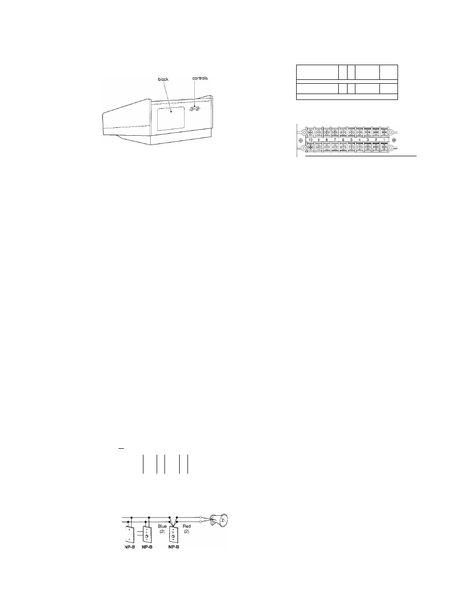
AP-5M terminals
n
w
ft©
fiS) r .... _____________5__4__3__2__^
©
ÍGÑD R C E E E E E E E l
AP-10M terminals
rGND R C E E E E E E E
I
Terminal block layout
-1~5
-6~10
1 ~ 5 or 1 ~ 10: Selective communication channels
E
C
R
GND
Common communication
“CALL” for calling other master
Occupied mode control
for grounding
AP-5M, AP-10M
As shown, station numbers 1 ~ 5 (top row) & 6 ~ 10 (2nd row)
are assigned, corresponding to the terminai numbers.
■ Cable
Use a
single-twisted pair cable for wiring between AP-M and each sub, homerun, or the other AP-M (In USA,
cable # 832202 specified)
■ Wiring
In single-master configuration, wiring is non-polarized for any type of sub. In dual-master system, wiring of
common sub(s), AS-3WA (2-call) and AP-M’s becomes polarized.
18Q horn speaker
When using an 8Q horn speaker and a call button is not required,
insert a 25 mfd non-polar capacitor in one side of the line. If a 25 mfd
capacitor is not available, two 50 mfd, 25V electrolytic capacitors may
be used when connected in series -i- to
+ ,
or - to -, as shown.
Making non-polar capacitor:
25mfd, 25V using two NP 50mfd, 25V
=ca
I wiring examples of NP-B call buttons
ForAS-3N
1. Multiple NP-B's
Biue(2)
AS-3N
To AP-M
mr
Red(2) ;
ft
Yo
NP-B NP-B NP-B
2. Local call switch
Doooc:
1W^
50
-
For 8Q horn
1. Multiple NP-B's
To AP-M WX
Biue(2)
Red(2) — T
o
2. Local call switch
To AP-M
ZZ
25^iF NP,25V
DOOOC
Call button
-
3
-