Accessory electric heater installation, For use with 559b self-contained cooling units), Introduction – Bryant 559B User Manual
Page 8: I. electric heater installation, Figure 3—power knockouts on external heater
Attention! The text in this document has been recognized automatically. To view the original document, you can use the "Original mode".
T
Accessory Electric Heater Installation
(For Use With 559B Self-contained Cooling Units)
INTRODUCTION
Single-phase electric heaters in 5-. through 15-KW sizes,
and three-phase electric heaters in 5.6- through 14.5-KW
sizes, are installed internally on 559B units. The 20- and
25-KW size single-phase heaters, and the 14.9- thru 25-KW
size three-phase heaters, are mounted externally on the
559B supply air connection. Do not use more than one
heater per unit. See Table I for heater model and 559B
usage.
I. ELECTRIC HEATER INSTALLATION
A. Internal Heaters
1. Remove fan section access panel.
2. Remove sheet metal plate covering heater installation
SCREW
CLEARANCE
HOLES (2)
(TOP AND BOTTOM)
HIGH-VOLTAGE LEADS
(CONNECTORS SUPPLIED)
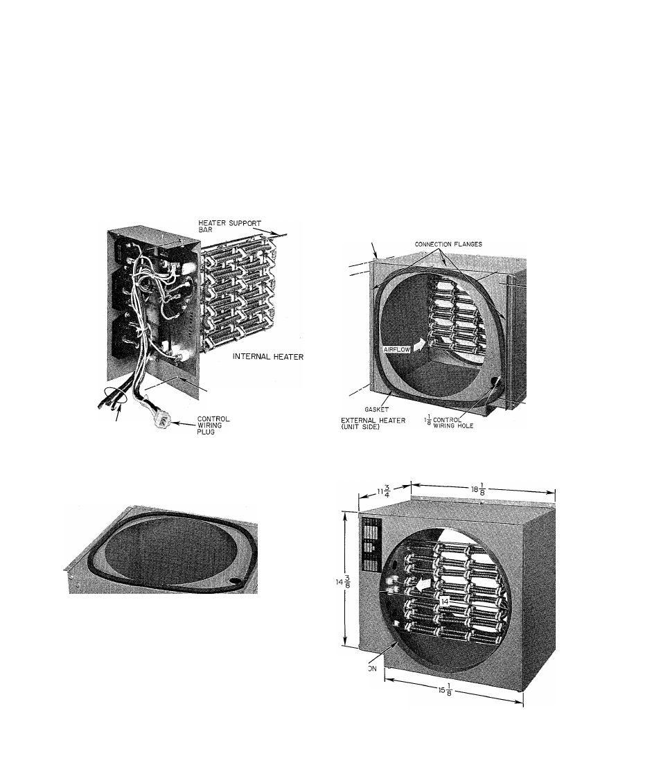
Figure 1—Internal Heater
•SERVICE
PANEL
I
5-LINE
'POWER
KNOCKOUT
EXTERNAL HE
mi
nn
(BOTTOM)
INLINE
“
power
KNOCKOUT
A73166
Figure 3—Power Knockouts on
External Heater
area (between evaporator fan discharge and supply air
connection). See Figure 5. Discard sheet metal plate.
3. Insert heater into opening provided.
NOTE: Ensure the heater support bar (Figures 1 and 5) en
ters the hole in the side of the fan discharge duct.
4. Fasten heater in place at top and bottom with two
sheet metal screws.
5. Attach heater wiring label provided to inside of fan
section access panel.
6. Installation is now ready for electrical connections.
See “Wiring”, Section III.
SCREW
CLEARANCE HOLES (7)
UNIT
IIRViCE
. „NEL
Figure 2—Entering Air Side of
External Heater
151
DUCT
CONNEC
FLANGE
EXTERNAL HEATER
(DUCT SIDE)
Figure 4—Duct Connection Side of
External Heater
-
8
-