Figure 9 — low-voltage field wiring (cooling only) – Bryant 559B User Manual
Page 7
Attention! The text in this document has been recognized automatically. To view the original document, you can use the "Original mode".
MODEL 883C
THERMOSTAT P/N34427DP78
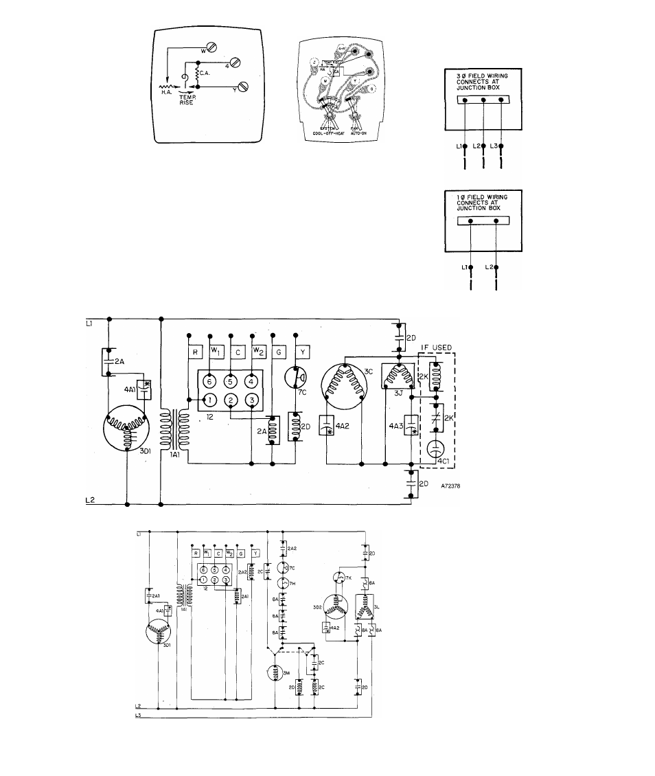
-FACTORY WIRING
- FIELD LOW-VOLTAGE WIRING
•FIELD HIGH-VOLTAGE WIRING
THERMOSTAT & SUBBASE
P/N 34427D03O
® Ç) ©
---------^—h
THERMOSTAT
CONNECTIONS
©
©
® ©
©
® © (^ Ç>
t—r
©
® ©
I
o
©
© ©
COLOR-CODED LEADS
(FROM UNIT)
located
inside
JUNCTION BOX
A72409
Figure 9 — Low-Voltage Field Wiring (Cooling Only)
Figure 10—559B-024, -020, -030, & -036 Wiring Diagram, 230-60-1
LEGEND
1A1-Control Transformer
1A2-460- to 230-V Transformer
2A-Cooling Fan Relay
2A1-Cooling Fan Relay
2A2-Cooling Relay
2C-Holding Relay
2D-Compressor Contactor (2 pole)
2K-Start Relay
2M-Compressor Contactor (3 pole)
3C-Condenser Fan Motor
3D1-Blower Motor
3D2-Two-speed Condenser Fan
Motor
3J-Compressor Motor with
Internal Protection
3L-Compressor Motor with
Internal Protection
3M-Timer Motor
4A1-Blower Motor Run Capacitor
4A2-Condenser Motor Run Capacitor
4A3-Compressor Motor Run
Capacitor
4C1-Compressor Motor Start
Capacitor
7C-Low-Pressure Switch
7H-lnternal Compressor Thermostat
7K-Low-Ambient Condenser Fan
Switch
8A-Com pressor Motor Overload
12-Receptacle
Figure 11 — 559B-048 Wiring Diagram, 208- or 230-60-3
-
7
-