Table i—ratings and performance, Table ii—filter dimensions – Bryant 559B User Manual
Page 3
Attention! The text in this document has been recognized automatically. To view the original document, you can use the "Original mode".
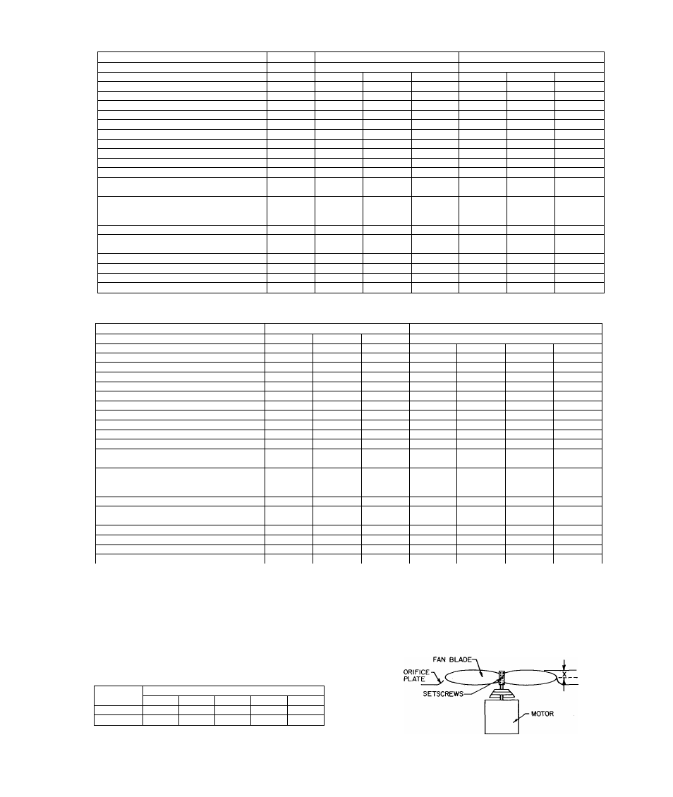
TABLE I—RATINGS AND PERFORMANCE
MODEL
559B-024-E
559B-030-E
5S9B-036-E
Rated Cooling Capacity* Btuh
24,000
30,000
35,000
Nameplate Voltage-Freq-Phase
230-60-1
230-60-1
208-60-3
230-60-3
230-60-1
208-60-3
230-60-3
Operating Voltage Range
207-254
207-254
187-229
207-254
207-254
187-229
207-254
Compressor Motor FLA
15.7
19.5
12.3
11.1
24.0
15.2
14.0
Locked Rotor Amps
72
88
70
60
100
80
70
Condenser Fan Motor** HP
1/5
1/5
1/5
1/5
1/4
1/4
1/4
Full Load Amps
1.3
1.3
1.4
1.3
1.8
2.1
1.8
Evaporator Blower Motor** HP
1/4
1/3
1/3
1/3
1/3
1/3
1/3
Full Load Amps
2.0
3.1
2.9
3.1
3.6
3.8
3.6
Rated Total Power Consumption KWH
3.5
4.6
4.6
4.6
5.7
5.7
5.7
Electrical Connections
Unit Full Load Amps
19.0
23.9
16.6
15.5
29.4
21.1
19.4
Unit Ampacity for Electrical
Conductor Sizing
22.9
28.8
19.7
18.3
35.4
24.9
22.9
Min Branch Circuit Wire
Size 60°C Temp Rating Copper
Conductor*** AWG No.
10
10
12
12
8
10
10
Max Line Length**** Ft
119
95
92
110
122
115
142
Largest Wire Size Line-Voltage Con
nections Will Accommodate AWG No.
4
4
4
4
4
4
4
Max Branch Circuit Fuse Size Amps
25
30
25
20
40
30
25
Refrigerant type/lbs-ozs
R-22/2-6
R-22/3-0
R-22/3-0
R-22/3-0
R-22/3-10
R-22/3-10
R-22/3-10
Evaporator Airflow CFM
900
1125
1125
1125
1350
1350
1350
Approximate Shipping Weight lbs
265
285
285
285
305
305
305
MODEL
559B-042-E
559B-048-E
Rated Cooling Capacity* Bfuh
42,000 .
41,000
42,000
48,000
Nameplate Voltage-Freq-Phase
230-60-1
208-60-3
230-60-3
230-60-1
208-60-3
230-60-3
460-60-3
Operating Voltage Range
207-254
187-229
207-254
207-254
187-229
207-254
414-508
Compressor Motor FLA
25.0
16.9
15.3
26.5
20.9
18.0
9.1
Locked Rotor Amps
111
92
92
118
90
78.5
39.3
Condenser Fan Motor** HP
1/4
1/4
1/4
1/4
1/4
1/4
1/4
Full Load Amps
1.8
2.1
1.8
1.9
2.1
1.8
1.8
Evaporator Blower Motor** HP
1/2
1/2
1/2
1/2
1/2
1/2
1/2
Full Load Amps
4.2
4.4
4.2
4.9
5.1
4.9
4.9
Rated Total Power Consumption KWH
6.3
6.3
6.3
7.2
7.2
7.2
7.2
Electrical Connections
Unit Full Load Amps
31.0
23.4
21.3
33.3
28.1
24.7
15.8
Unit Ampacity for Electrical
Conductor Sizing
37.4
27.6
25.1
40.0
33.3
29.2
18.1
Min Branch Circuit Wire
Size 60°C Temp Rating Copper
Conductor*** AWG No.
8
10
10
8
8
10
12
Max Line Length**** Ft
116
103
130
108
137
112
225
Largest Wire Size Line-Voltage Con
nections Will Accommodate AWG No.
4
4
4
4
4
4
4
Max Branch Circuit Fuse Size Amps
40
30
30
45
35
30
20
Refrigerant type/lbs-ozs
R-22/4-13
R-22/4-13
R-22/4-13
R-22/4-11
R-22/4-11
R-22/4-11
R-22/4-11
Evaporator Airflow CFM
1570
1570
1570
1800
1800
1800
1800
Approximate Shipping Weight lbs
345
345
345
367
367
367
367
*Rated in Accordance with ARI Standard 210-66.
**Condenser fan and evaporator motors are single phase.
***If other than 60 °C copper conductor is used, determine size from unit ampacity and the National Electrical Code. Voltage drop of
wire must be less than 2% of unit rated voltage.
****Wire length shown is measured one way along the wire path between unit and service panel for minimum voltage drop.
X = Size 024, 030, & 036................................................................................ 1-3/4 in.
Size 042 & 048 ............................................................................................ 2 in.
TABLE II—FILTER DIMENSIONS
Unit Size
Minimum Filter Size or Equivalent, Inches
024
030
036
042
048
Disposable
16x20x1
20x20x1
20x25x1
25x25x1
25x25x1
Permanent
12x20x1
16x20x1
20x20x1
20x20x1
20x25x1
Figure 4—Required Condenser
Fan Position
-
3
-