Table ii—heater electrical data, B. control wiring (24v), C. thermostat leads – Bryant 559B User Manual
Page 10: Iv. service
Attention! The text in this document has been recognized automatically. To view the original document, you can use the "Original mode".
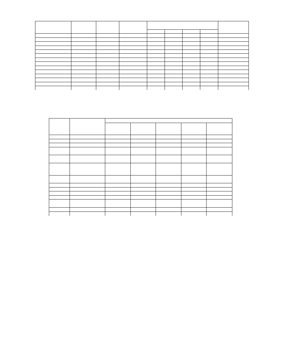
TABLE I—HEATER DATA & USAGE
Heater
Bryant
Voltage-
Hertz-
Btuh Output
Size Unit
Model No.
P/N
KW*
Phase
208V
230V
240V
480V
Used With
88EA0050CA00
7O181D01
5
240-60-1
—
15,673
17,065
—
024, 030, & 036
88EA0075CAOO
7O181D02
7.5
240-60-1
—
23,509
25,598
—
024 thru 048
88EA0100CA00
7O181D03
10
240-60-1
—
31,345
34,130
—
024 thru 048
88EA0150CA00t
7O181D04
15
240-60-1
_
47,018
51,195
—
030 thru 048
88EA12O0CAOOt
7O181D05
20
240-60-1
—
62,690
68,260
—
042 & 048
88EA1250CA00t
70181D06
25
240-60-1
—
78,363
85,325
—
,042 & 048
88EA1250LA00t
7O181D08
25
208-60-3
85,325
—
—
—
042 & 048
88EA0075EA00
7O181D01O
5.6/7.5
208/240-60-3
19,227
23,509
25,598
—
030 thru 048
88EA0100EAOO
7O181D011
7.5/10
208/240-60-3
25,635
31,345
34,130
—
030 thru 048
88EA0145EA00
7O181D012
10.9/14.5
208/240-60-3
37,171
45,450
49,489
—
030 thru 048
88EA1198EAOOt
7O181D013
14.9/19.8
208/240-60-3
50,758
62,063
67,577
—
042 & 048
88EA1250EA00t
7O181D014
18.75/25
208/240-60-3
64,089
78,363
85,325
—
042 & 048
88EA0160FA00
7O181D016
10
480-60-3
—
—
—
34,130
048
88EA1200FA00t
7O181D018
20
480-60-3
—
-
—
68,260
048
*At rated voltage.
tThese heaters are wired for two-stage heating. Remaining heaters are wired for single-stage heating.
NOTE:
The 18.75/25- and 25-KW heaters must be field-connected for two-stage operation. All other heaters wired for two-stage heating
may be field-connected for single- or two-stage operation.
TABLE II—HEATER ELECTRICAL DATA
KW
Voltage-
Hertz-
Phase-
Branch Circuit
No. of
Circuits
FLA
(each)
Wire
Size*
(AWG No.)
Max Wire
Length
(ft)**
Fuse
Amps
5t
240-60-1
1
20.8
10
45
30
7.5t
240-60-1
1
31.2
8
45
40
lot
240-60-1
1
41.7
6
55
50
15t
240-60-1
2
41.7
6
55
50
20.8
10
45
30
20
240-60-1
2
41.7
6
55
50
41.7
6
55
50
25
240-60-1
3
41.7
6
55
50
41.7
6
55
50
20.8
10
45
30
25
208-60-3
2
34.7
6
55
45
34.7
6
55
45
5.6/7.5t
208/240-60-3
1
15.6/18.0
12/10
49/49
20/25
7.5/1 Ot
208/240-60-3
1 ■
20.8/24.0
10/10
59/59
30/30
10.9/14.5t
208/240-60-3
1
30.2/34.9
8/6
63/63
40/45
14.9/19.8
208/240-60-3
1
41.3/47.6
6/4
46/73
60/60
18.75/25
208/240-60-3
2
26.0/30.1
8/8
47/47
35/40
26.0/30.1
8/8
47/47
35/40
lot
480-60-3
1
12.0
14
59
15
20
480-60-3
1
24.0
10
74
30
tThese heaters are internally installed. All others are externally installed.
*Based on 60°C copper wire. If other than 60°C copper conductor is used, determine size from unit ampacity and the
National Electrical Code. Voltage drop of wire must be less than 2% of unit rated voltage.
**Length shown is for one way along the wire path from unit to service panel for minimum voltage drop.
B. Control Wiring (24V)
Between Heater and 559B
A low-voltage control-wiring plug is provided on the heater
for connection to the receptacle in the 559B control-wiring
terminal box.
On internal heater installations, extend the control-wiring
plug through the hole provided in the 559B control-wiring
terminal box and connect to the receptacle. On external
heaters, feed the plug through the control-wiring hole
provided in the heater cabinet (Figures 2 and 6) and into
the 559B. Extend the plug into the 559B control-wiring ter
minal box and connect the plug to the receptacle.
NOTE: When heater installation is completed, be sure to
seal holes around all electrical openings to prevent air
leakage.
C. Thermostat leads
The thermostat leads are brought through the grommeted
hole, provided in the 559B, into the control-wiring terminal
box. Connect the thermostat leads to the low-voltage
pigtails. See Figure 8 or 9 for thermostat connection
diagrams.
Tape
unused pigtails separately. When
aluminum field wire is used, lubricate splices with a
suitable splice compound, and use approved copper-to-
aluminum splice connectors. Set the thermostat heat an
ticipator as described in “Determining Heat Anticipator
Setting”, Section V.
IV. SERVICE
A. Limit Switch
The limit switch provides overtemperature protection. A
switch malfunction prevents the heating elements from
being energized. Replace the limit switch if a malfunction
occurs.
B. Time-Delay Relay
The 14.9- through 25-KW heaters are sequenced. The time-
-
10
-