Gaseous carburetion, Fuel supply lines, Excess flow valve – Generac Power Systems 0940-1 User Manual
Page 28: Leakage tests, Fuel supply lines excess flow valve leakage tests
Attention! The text in this document has been recognized automatically. To view the original document, you can use the "Original mode".
NOTE: Recommended MINIMUM gas flow rate for all
air-cooled Impact-34 plus series generators is 67 cubic
feet per hour.
IMPORTANT: IF AN EXISTING PRIMARY GAS REG
ULATOR DOES NOT HAVE A SUFFICIENT FLOW
CAPACITY FOR THE GENERATOR AND OTHER
GAS APPLIANCES IN THE CIRCUIT, (a) INSTALL A
PRIMARY
REGULATOR
WITH
ADEQUATE
FLOW
RATE, OR (b) INSTALL A SEPARATE REGULATOR
RATED AT LEAST 67 CUBIC FEET PER HOUR. THE
INLET SIDE OF ANY PRIMARY REGULATOR THAT
SUPPLIES
THE
GENERATOR
MUST
CONNECT
DIRECTLY TO GAS TANK PRESSURE. DO NOT
TEE THE GENERATOR LINE INTO A GAS CIRCUIT
FEEDING OTHER APPLIANCES.
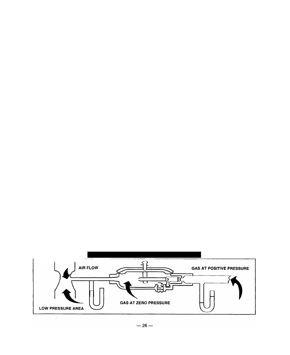
GASEOUS CARBURETION
LP gas vapors should be supplied to the generator
regulator inlet at about 11 inches water column (posi
tive pressure). The engine piston draws air in during
the intake stroke (Figure 29). This air passes through
a carburetor venturi which creates a low pressure that
is proportional to the quantity of air being pumped.
The low pressure from the carburetor venturi acts on
the regulator diaphragm, to pull the diaphragm toward
the source of low pressure. A lever attached to the
diaphragm opens a valve to permit gas flow through
the carburetor.
The greater the air flow through the carburetor venturi,
the lower the pressure at the venturi throat, the greater
the diaphragm movement and the greater the move
ment of the regulator valve. The more the regulator
valve opens, the greater the gas flow that is propor
tional to air flow through the carburetor.
The following facts about the secondary regulator must
be emphasized:
• The regulator must be sensitive to venturi throat pressure
changes throughout the operating range.
• The regulator must be properly adjusted so it will stop the
flow of gas when the engine is not running (no air flow
through the carburetor).
• The slightest air flow (and vacuum) in the venturi throat
should move the regulator valve off its seat and permit gas
to flow.
FUEL SUPPLY LINES
• Propane gas lines must be accessible, but protected
against possible damage.
• Do NOT connect electrical wiring to any propane gas fuel
line or run wiring alongside the lines.
• Route gas lines away from hot engine exhausts.
• Retain gas lines with metal clamps that do not have sharp
edges.
• Install an approved length of flexible hose between the
gaseous fuel solenoid valve and riaid fuel supply lines.
The flexible line must be non-metallic, non-organic and
non-conductive. It must be approved tor use with LP gas.
EXCESS FLOW VALVE
Propane gas tanks should have an excess flow valve,
according to NFPA 501C, Paragraph 3-4.4. This valve
and the gas lines must be carefully sized so the valve
will close when a fuel line is severed or broken.
Consult the Natural-LP Gas Association for information
and limitations of excess flow valves.
Manual shutoff valves on the supply tank and else
where in the system must be fully open when operat
ing the generator. The excess flow valve functions
properly only if all valves are fully open.
LEAKAGE TESTS
Do not place the generator into service until you have
properly tested the gas system for leaks. To test the
system, you need a separate source of 12 volts DC to
open the gaseous fuel solenoid valve.
The leak test must comply fully with NFPA, Paragraph
318. All connections, hoses, valves, regulators, fitting,
and other fuel system parts must be tested under gas
or air pressure of not less than 90 psi (620kPa). while
using soap and water or equivalent solution to check
for leaks. Other approved methods of testing for leaks
may be used, if appropriate. DO NOT USE ANY
FLAME TO TEST FOR LEAKS.
DANGER: Gaseous fuel lines between the tank and
the secondary regulator are under a positive pres
sure (about 11 inches water column). Gas pressure
at the outlet side of the secondary regulator, howev
er, is a negative pressure (about 1-inch water col
umn) and can draw flame inside a line or fitting and
cause an explosion.
Figure 29 — Propane Gas Carburetion Diagram