Pneumatic tire pressure, Operation, Controls – MTD 315-860-000 User Manual
Page 9
Attention! The text in this document has been recognized automatically. To view the original document, you can use the "Original mode".
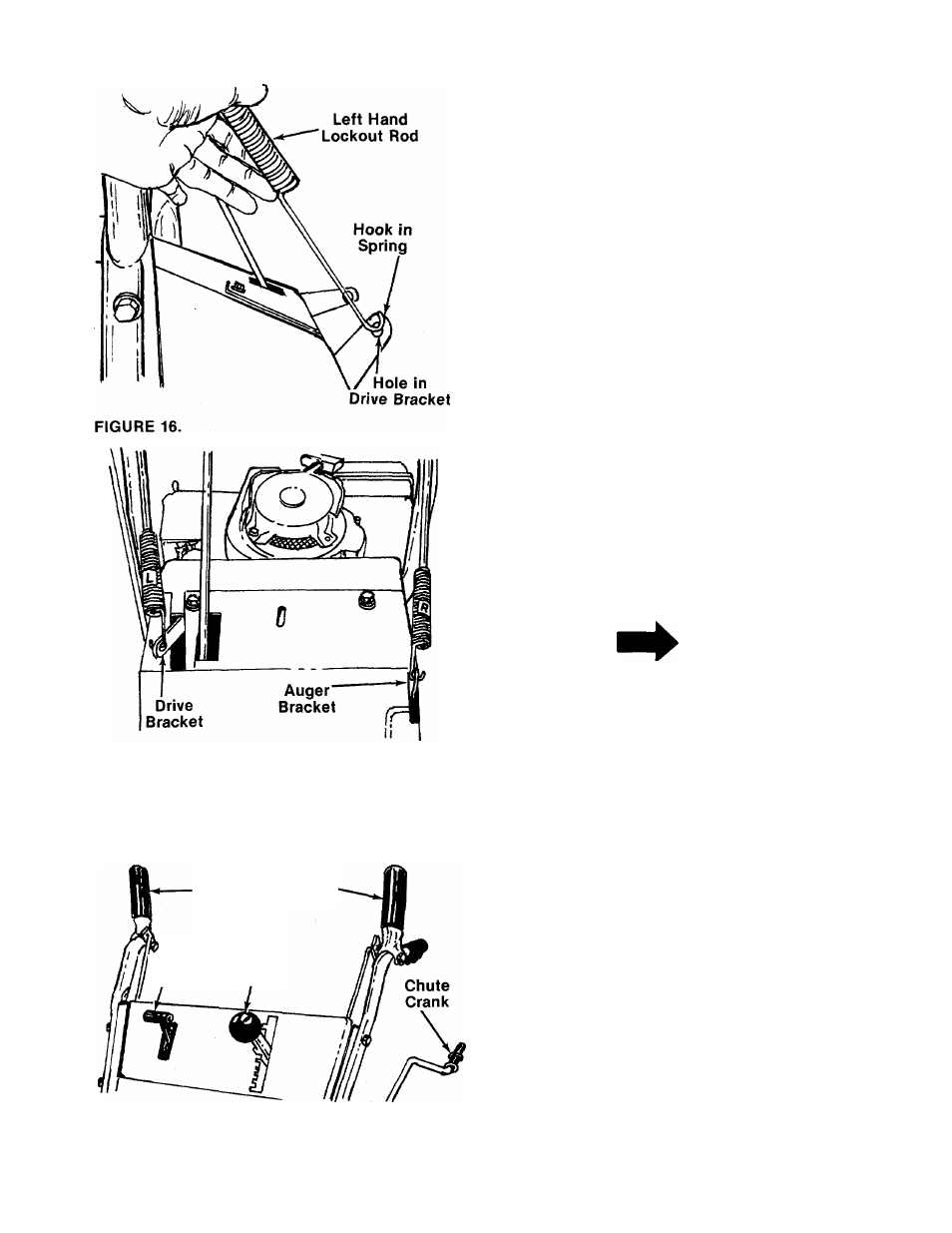
21. Swing the left hand lockout rod down and
simply hold it beside the drive bracket.
Do not
pull on spring.
Do not
move bracket.
The hook
on the end of the spring must line up with the
center of the hole in the drive bracket.
See
-------figure 16.
If it does not, adjust the nut on the lockout rod
until the hook on the spring aligns with the
hole in the bracket as shown in figure 16.
Hook spring into drive bracket. See figure 17.
22. Adjust the right hand lockout rod in the same
manner as the left hand lockout rod. Refer to
Step 21. When adjustment is correct, hook the
-------spring into the auger bracket. See figure 17.
PNEUMATIC TIRE PRESSURE
The tires are over inflated for ship
ping purposes. Check pressure and
reduce to 15 to 20 p.s.i.
NOTE
If the tire pressure is not equal
in both tires, the unit may pull to
one side or the other.
FIGURE 17.
OPERATION
CONTROLS
Auger
Drive
Clutch
Clutch
'
Throttle
Shift
Control Lever
FIGURE 18.
Shift Lever
(See figures 18 and 19)
The shift lever is located on the left hand side of
handle panel. The shift lever may be moved into
one of eight positions. Run engine with throttle in
the fast position. Use the shift lever to determine
ground speed.
a. Center position (N)—“NEUTRAL."
b.
Forward position—One of five (5) forward
speeds. Position number one (1) is the slowest.
Position number five (5) is the fastest.
c.
Rear position—Two reverse (R) speeds. “R”
nearest the neutral (N) position is the slower of
the two.