MTD 315-860-000 User Manual
Page 8
Attention! The text in this document has been recognized automatically. To view the original document, you can use the "Original mode".
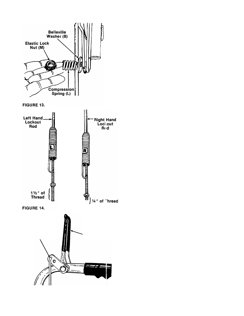
18. Secure with belleville washer (B) (cupped side
goes against shift lever), compression spring
(L) and elastic lock nut (M). See figure 13.
Tighten lock nut until compression spring
holds the shift lever into detent slot on handle
panel.
19. The lockout rods are labeled “L” and “R” for
the left and right hand sides of the unit.
Approximate
initial settings for the lockout
rods are as follows; The left hand lockout rod
for the drive clutch should have approximately
IV
2
inches of thread showing below the nut.
The right hand lockout rod for the auger
clutch should have approximately V
a
inch of
thread showing below the nut. See figure 14.
FINAL
ADJUSTMENT
MUST
BE
MADE
AS
DESCRIBED IN STEPS 21 AND 22.
If the left
hand lockout rod is not adjusted correctly, the
shift lever cannot be shifted past neutral. If
the right hand lockout rod is not adjusted cor
rectly, the augers will not stop rotating.
Hook in Lockout
Rod is to the
Outside of Unit
Clutch
Grip
20
.
Hook the right hand lockout rod (labeled “R”)
into the hole provided in the right hand clutch
grip (auger clutch). Hook the left hand lockout
rod (labeled “L”) to the left hand clutch grip
(drive clutch). See figure 15. The hook is to the
outside of the unit.
FIGURE 15.