Note – MTD 315-860-000 User Manual
Page 6
Attention! The text in this document has been recognized automatically. To view the original document, you can use the "Original mode".
11. Place hex bushing (I) into bracket beside the
chute assembly. Position the hex bushing so
the hole in the bushing is close to the chute
-------assembly. See figure 7.
12. Place flat washer (G) on the end of the chute
crank. Insert the chute crank into the hole in
the hex bushing so that the spiral on the chute
crank engages the teeth on the chute assem
bly. Place large flat washer (H) on the end of
the chute crank. Insert cotter pin (J) into hole
in the end of chute crank. Secure by bending
the ends of cotter pin in opposite directions.
FIGURE 7.
FIGURE 8.
13.
Assembie the throttie control to the handle
panel as follows.
A.
Hold
the
throttle
control
assembly
beneath the handle panel. Turn the control
sideways and insert the lever up through
the wide portion of the slot on the handle
panel. See figure 8A.
B. After the end of the lever is through the
slot, turn and then tip the control forward
as shown in figure 8B to slide it through
the slot.
NOTE
The lever must be all the way to the
back
of
the
control
housing
as
shown in figure 8B.
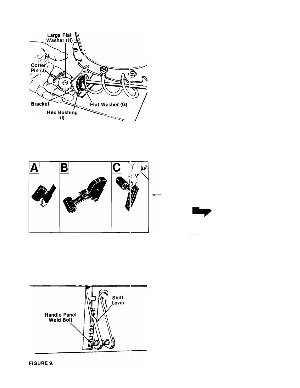
C. Push the control back into the slot in the
handle panel and press in place. Be certain
the control is locked securely into the slot.
A
14.--- Place shift lever (Q) through slot in handle
panel, making sure flared edge of shift lever
faces the detents on handle panel. Place the
hole in the end of the shift lever over the han-
------- die panel weld bolt. See figure 9.