Figure 31 – MTD 315-860-000 User Manual
Page 16
Attention! The text in this document has been recognized automatically. To view the original document, you can use the "Original mode".
Engine
Pulley
Auger
Drive
Belt
FIGURE 28.
5.
Remove the top screws and lock washers
which attach the auger housing asserr bly to
the frame assembly. A 9/16" wrench is re
quired. See figure 29.
Lift Up
on Handles
(Auger Clutch
Grip Squeezed)
FIGURE 30.
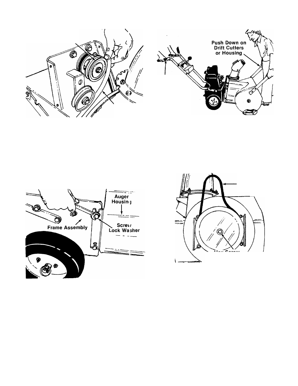
7. To Remove Auger Drive Belt:
a.
Remove the hex screw and belleville
washer from the center of the pulley on the
auger housing. Remove the pulley. See
figure 31. Be careful not to lose the key.
\W
Auger Drive
Belt
Pulley
'--^Hex
Screw
/
i
Belleville Washer
y?
FIGURE 31.
FIGURE 29.
6. To separate the auger housing from the frame
assembly, two people are required. On 3 per
son is in the operating position. Squeeze the
auger clutch grip (right hand) as you raise up
on the handles. See figure 30. The other per
son is in front of the unit. Push down cn the
housing or optional drift cutters. See figure
30. The unit will separate into two pieces.
b. Remove and replace auger drive belt.
c.
Reassemble pulley to auger housing with
hex screw and belleville washer (cupped
side is toward the pulley). Be certain key is
in place on shaft.
8. To Remove Drive Belt:
a.
Remove the cotter pin which holds the
linkage rod to the idler bracket assembly.
See figure 32.
b.
Unhook extension spring from the engine
plate. See figure 32.
16