Figure 20, Starting instructions – MTD 315-860-000 User Manual
Page 10
Attention! The text in this document has been recognized automatically. To view the original document, you can use the "Original mode".
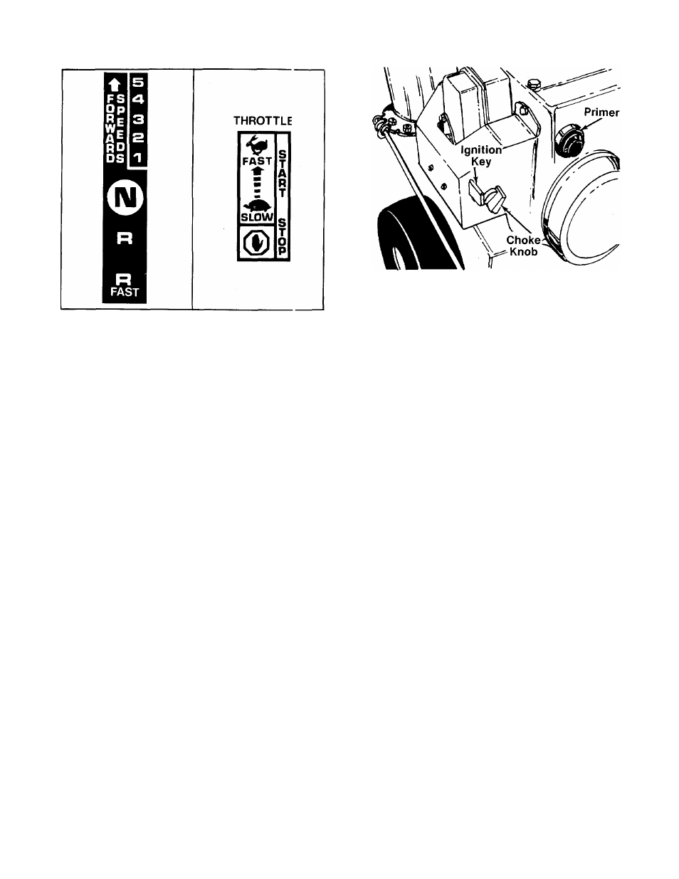
FIGURE 19.
FIGURE 20.
Throttle Control
(See figures 18 and 20)
The throttle control is located on the righ hand
side of the handle panel. It regulates the speed of
the engine.
Drive Clutch
(See figure 18)
The drive clutch is located on the left handle.
Squeeze the clutch grip to engage drive. Release
to stop.
Auger Clutch
(See figure 18)
The auger clutch is located on the right handle.
Squeeze the clutch grip to engage the cugers.
Release to stop the snow throwing action.
Chute Crank
(See figure 18)
The chute crank is located on left hand side of the
snow thrower.
To change the direction in which snow is th rown,
turn chute crank as follows:
1. Crank clockwise to discharge to the left.
2. Crank counterclockwise to discharge o the
right.
Safety Ignition Switch
(See figure 21)
The ignition key must be inserted in the s witch
before the unit wili start. Remove the ignition key
when snow thrower is not in use.
FIGURE 21.
STARTING INSTRUCTIONS
1.
Remove dipstick. Fill crankcase with oil. Oil
level must be to full mark on dipstick. Refer to
separate
engine
manual
packed
with
your
snow thrower.
2.
Fill
fuel
tank
with
fresh,
clean
regular
gasoline.
Ai
WARNING
Never fill fuel tank indoors, with en
gine running or while engine is hot.
3. Attach spark plug wire to spark plug.
4. Insert ignition key (do not turn).
5. Place shift lever in “NEUTRAL” (N) position.
6. Place throttle control in “START” (fast) posi
tion.
AC
WARNING
Never run engine indoors or in en
closed poorly vented area. Engine
exhaust gases contain carbon mon
oxide: an odorless and deadly gas.
7.
Start engine, following appropriate instruc
tions:
A. Cold engine start (engine has not been run
recently).
1. Turn choke knob to “full” position. See
figure 21.
2. Push primer two (2) or three (3) times.
See figure 21.
10