Maintenance, Augers, Shave plate and skid shoes – MTD 315-860-000 User Manual
Page 15: Belt removal and replacement
Attention! The text in this document has been recognized automatically. To view the original document, you can use the "Original mode".
MAINTENANCE
AUGERS
The augers are secured to the spiral shaft with two
hex boits and hex lock nuts (see Ref. Nos. 40 and
50 on page 24). if you hit a foreign object or ice
jam, the snow thrower is designed so that the hex
bolts will shear.
If the augers will not turn, check to see if the hex
bolts have sheared. Two replacement hex bolts
and hex lock nuts have been provided with the
snow thrower. For future use, order part number
710-0891 (hex bolt 5/16-18 x 1.75" long) and
712-0429 (hex insert lock nut 5/16-18 thread).
SHAVE PLATE AND SKID SHOES
The shave plate and skid shoes on the bottom of
the snow thrower are subject to wear. They should
be
checked
periodically
and
replaced
when
necessary. Skid shoes and shave plate are revers
ible for longer life. The skid shoes may also be in
verted to extend their life even further.
To remove shave plate, remove the carriage boits,
lock washers and hex nuts which attach it to the
snow thrower housing. Reassemble new shave
plate, making sure heads of the carriage bolts are
to the inside of the housing. Tighten securely.
To remove skid shoes, remove the four carriage
bolts, believille washers, and hex nuts which at
tach them to the snow thrower. Reassemble new
skid shoes with the four carriage bolts, believille
washers (cupped side goes against skid shoes)
and hex nuts.
BELT REMOVAL AND REPLACEMENT
Ac
WARNING
\
Remove the spark plug wire from
the spark plug and ground. Drain
gasoline from the fuel tank, or place
a piece of plastic film underneath
the gas cap to prevent gasoline from
leaking.
To remove and replace either the auger drive belt
or the drive belt, proceed with the following in
structions.
1.
Remove
the
chute
crank
at
the
chute
assembly by removing the cotter pin and flat
washer.
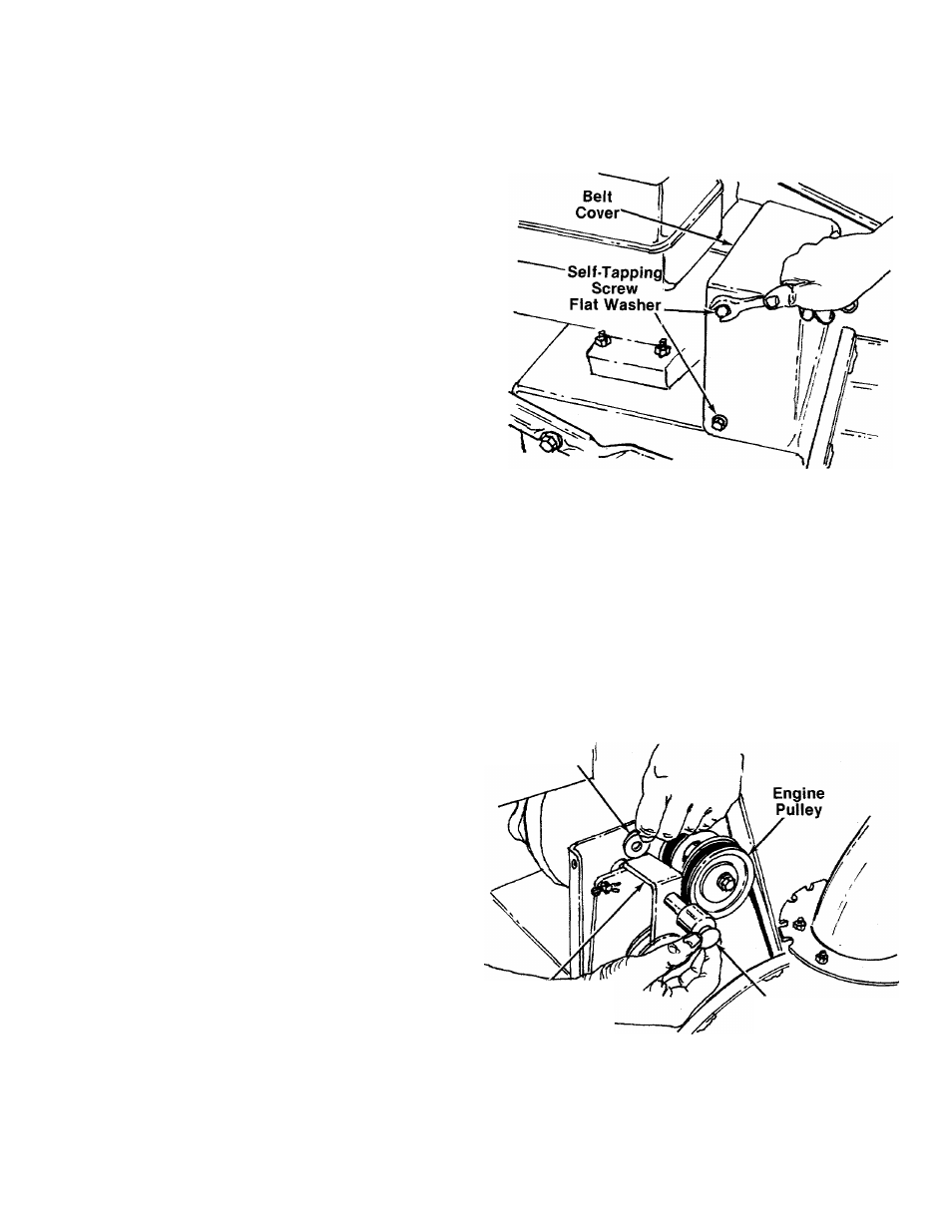
Remove the plastic belt cover on the front of
the engine by removing the three self-tapping
screws and flat washers. See figure 26.
FIGURE 26.
3. Remove the large shoulder bolt and spacer on
the right hand side of the engine puliey with
an adjustable wrench. Remove the shoulder
bolt
and
spacer
from
the
idler
bracket
assembly with one hand. Use the other hand
to catch the believille washer which is on the
shoulder bolt between the idler bracket and
engine plate. See figure 27.
;Belleville
Washer
Idler Bracket
Assembly
FIGURE 27.
Shoulder Bolt
Spacer
4. Slip the auger drive belt (the front belt) off the
engine pulley. See figure 28.
15