Maytag MED5591TQ1 User Manual
Page 16
Attention! The text in this document has been recognized automatically. To view the original document, you can use the "Original mode".
Alternate installations for close clearances
Venting systems come in many varieties. Select the type best for your installation. Two close-
clearance installations are shown. Refer to the manufacturer's instructions.
Determine vent path
B
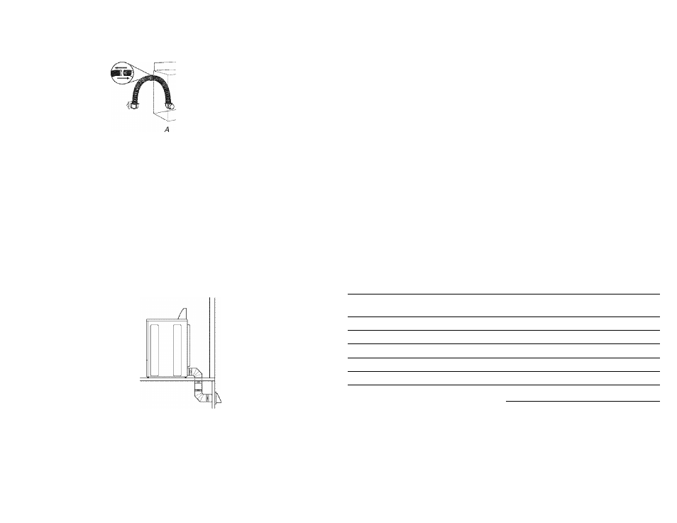
A. Over-the-top inftaliation (ako available with one offset elbow)
B. Periscope installation
NOTE: The following kits for close clearance alternate installations are available for purchase.
Please see the "Assistance or Service" section to order.
■ Over-the-Top Installation:
Part Number 4396028
■
Periscope Installation (For use with dryer vent to wall vent mismatch):
Part Number 4396037 - 0" (0 cm) to 18" (45,72 cm) mismatch
Part Number 4396011 - 1 8" (45.72 cm) to 29" (73.66 cm) mismatch
Part Number 4396014 - 29" (73.66 cm) to 50" (127 cm) mismatch
Special provisions for mobile home installations
The exhaust vent must be securely fastened to a noncombustible portion of the mobile home
structure and must not terminate beneath the mobile home. Terminate the exhaust vent
outside.
Select the route that will provide the straightest and most direct path outdoors.
Plan the installation to use the fewest number of elbows and turns.
When using elbows or making turns, allow as much room as possible.
Bend vent gradually to avoid kinking.
Use the fewest 90° turns possible.
Determine vent length and elbows needed for best drying performance
■ Use the Vent system chart below to determine type of vent material and hood
combinations acceptable to use.
NOTE: Do not use vent runs longer than those specified in the Vent system chart. Exhaust
systems longer than those specified will;
■ Shorten the life of the dryer.
■
Reduce performance, resulting in longer drying times and increased energy usage.
The Vent system chart provides venting requirements that will help to achieve the best drying
performance.
Vent systems charts
When using only one type of metal vent:
Use the following chart to help you determine your maximum vent length based on the
number of 90° [urns or elbows you will rteed artd lire type of verrt (rigid arrd/or flexible
metal) you will use.
Vent system chart
Number of 90“
turns or elbows
Rigid metal vent
Flexible metal vent
0
1 '0 ft (36.6 m)
40 ft (12,2 m)
1
11 0 ft (33.5 m)
37 ft (11,3 m)
2
1 00 ft (30.5 m)
33 ft (10,1 m)
3
90 ft (27.4 m)
30 ft (9.1 m)
4
80 ft (24.4 m)
27 ft (8.2 m)
5
70 ft (21,3 m)
23 ft (7.0 m)
When using a combination of rigid and flexible metal vent:
Use the following charts to help you determine your maximum vent length based on the
number of 90° turns or elbows you will need.
■
Determine the number of elbows or turns you will need.
■
Determine the length of the fully extended flexible metal vent you will use. Find the
column that has the nearest number of feet to what you will be using.
■ Match the number of turns or elbows with the length of the fully extended flexible
metal vent you will use to find the maximum length of rigid metal vent you can use.
16