Maytag MED5591TQ1 User Manual
Page 13
Attention! The text in this document has been recognized automatically. To view the original document, you can use the "Original mode".
B c
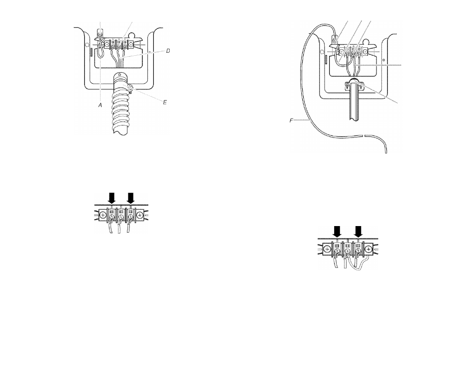
A. Neutral ground wire
B. External ground conductor screw
C. Center silverwohred terminal block screw
D. Neutral wire (white or center wire)
E. yC (1.9 cm) UL listed strain relief
3, Place the hooked ends of the other power supply cable wires under the outer terminal
block screws (hooks facing rightj. Squeeze hooked ends together. Tighten screws.
4, Tighten strain relief screw.
5, Insert tab of terminal block cover into slot of dryer rear panel. Secure cover with hold
down screw.
6, You have completed your electrical connections. Now go to "Venting Requirements."
- D
""E
A. External ground conductor screw
B. Neutral ground wire
C. Center silver-colored terminal block screw
D. Neutral wire (white or center wire)
E. %" (1.9 cm) UL listed strain relief
E Grounding path determined by a qualified electrician
3. Connect the other wires to outer terminal block screws. Tighten screws.
Optional 3-wire connection
Use for direct wire or power supply cord where local codes do not permit connecting
cabinet-ground conductor to neutral wire.
1, Remove center silver-colored terminal block screw.
2, Remove neutral ground wire from external ground conductor screw. Connect neutral
ground wire and the neutral wire (white or center wire) of power supply cord/cable under
center, silver-colored terminal block screw. Tighten screw.
4. Tighten strain relief screws.
5. Insert tab of terminal block cover into slot of dryer rear panel. Secure cover with hold
down screw.
6. Connect a separate copper ground wire from the external ground conductor screw to an
adequate ground.
13