To reassemble and replace needle thread tension – SINGER 319K User Manual
Page 43
Attention! The text in this document has been recognized automatically. To view the original document, you can use the "Original mode".
41
SHOULD IT BECOME NECESSARY TO REMOVE
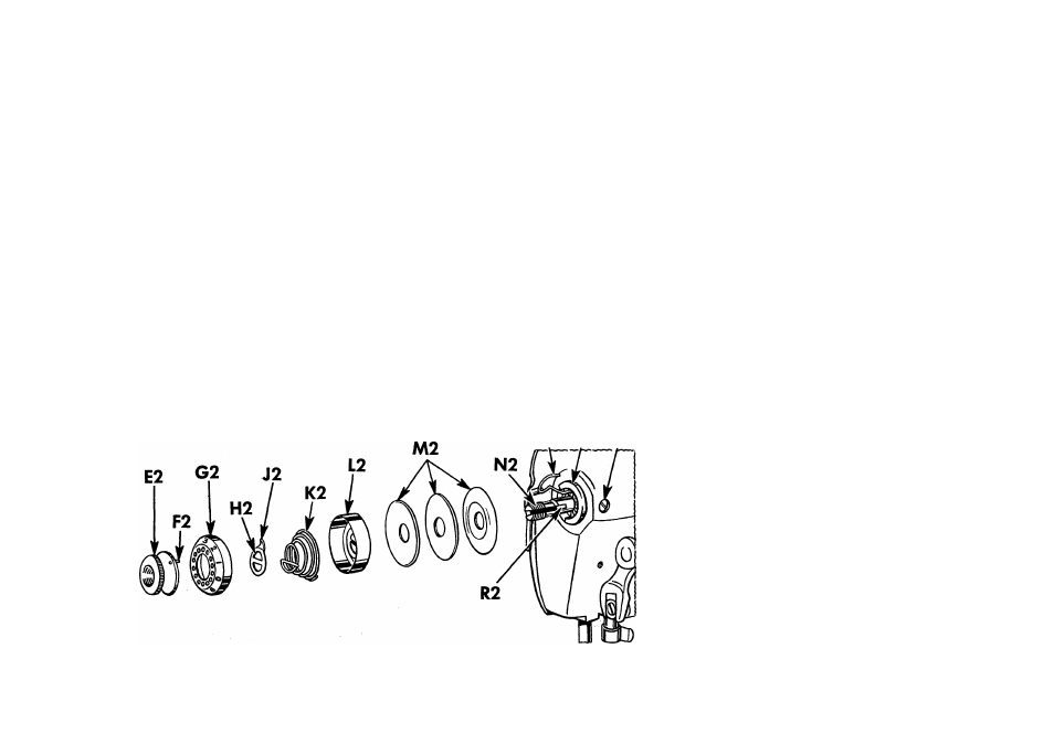
AND DISASSEMBLE NEEDLE THREAD TENSION
Turn thumb nut E2 to the left (counter-clockwise)
until "0” on dial G2 stops at center line on indicator
L2. To separate pin F2 in thumb nut E2 from dial
G2, press in dial, unscrew thumb nut and remove it.
Then remove tension parts from stud N2, as shown in
Fig. 69. Do not remove stud N2.
TO REASSEMBLE AND REPLACE NEEDLE THREAD TENSION
Make sure that tension releasing pin R2 is in place in
stud N2. Replace the tension parts on the stud N2 as
follows: Replace the three tension discs M2 with the
thick flat disc separating the convex surfaced discs.
Then replace the indicator L2, open side out, on stud
with plus and minus signs at top, then insert tension
spring K2 in indicator with the first (half) coil of this
spring straddling the lower half of the stud. Place stop
02 P2 Q2
washer on stud with extension J2 above stud, so that
it clears the first (half) coil of tension spring. Next,
place dial G2 on stud with No. 2 opposite stop washer
extension J2, then push dial to compress tension
spring and at the same time screw thumb nut E2 on
stud, inserting pin F2 on nut in one of the holes in
dial G2. Then lower presser bar and turn thumb nut
E2 to left until "0” on dial G2 stops at center line on
indicator L2. Thread the tension and
pull thread through tension discs to
test amount of tension on thread at
"0” position.
At this point there should be a slight
pull on the thread to indicate that
there is a minimum tension which
gradually increases with the turning
of thumb nut E2 to the right, pro
viding a full range of tensions with
one revolution of the thumb nut. If
the pull is too strong for a minimum
tension, press in dial G2 to disen
gage pin F2 on nut from dial, and
Fig. 69. Needle Thread Tension Assembly