Sears 113.29003 User Manual
Page 9
Attention! The text in this document has been recognized automatically. To view the original document, you can use the "Original mode".
1. i^sen me aamptng
msewt
yrem i; wn
cwiti
cnannws
. (Item 2).
2. Adjust fufts {Item 3) by olternoHng loosening and tighten-
&)g
*0 that the channels ore moved up or down on the
odjustlng screws (Item 4) in the desired direction.
3. When chonnels ore properly odjusted the arbor wrench
will just contact the table lop when swung bock and forth
at Positions 1, 2, 3, ond 4 of Figure 9. tighten damping
screws (Item 1). Rechedt the four positions to insure that
no change has occurred.
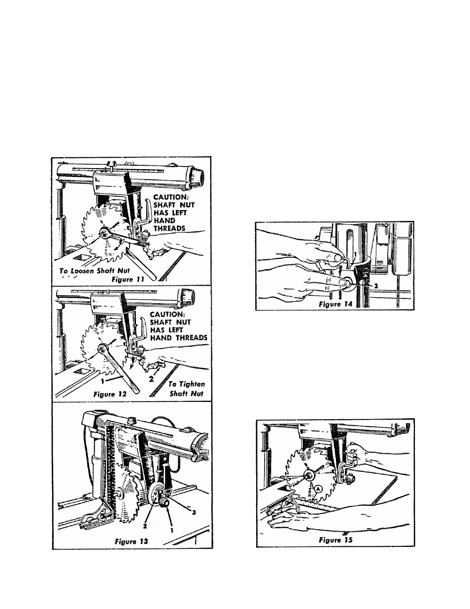
ATTACHING THi SAW tLADS
1. Remove shaft nut ond one loose collar,
2. Pioce saw blade on motor shaft taking core that sow
blade teeth are in some direction as shown in Figure 11 •
3. Replace other loose collar and shaft nut. Smooth face
of eolior mast be owoy from saw blade.
4. Use arbor wrench {Item 1, figure 12 on motor shaft nut
and shaft vrrench (Item 2, figure 12) on slot in motor shoft
to tighten shoft nut.
i^auAKiNts inc &AW etAite tnt lAOit lur
1. Place edge of combincrtion squore or accurate steel
square on table top ond position as shown in Figure 13.
Square must be held firmly ogainst fable top.
2. When blade is square to the table no light will be visible
betvreen square and face of taw blode. Do not allow
square fa rest on saw teeth.
If light is visible between steel square and face of saw
blade adjust as fallows:
o. Loosen bevel lock knob (Item 1, figure 13). Use 7/32
hex "1" wrench and slightly loosen four socket head
screws (Item 2, figure 13).
b. Hold motor shaft at one end and tilt motor in proper
direction until saw blade b square to fable top. Sec
Step 2 above,
c. Retighten socket heod screws (Item
2,
figure 13) and
bevel lock knob (Item 1, figure 13).
d. Recheck blade squareness to table top since tighten
ing of screws moy have shifted motor.
e. Indicolor (Item 3, figure 13) should read 0“ on bevel
index stole. If not, loosen screw and odjust indkertor.
Retighten screw,
CHECKING COLUMN TUBE KEY
If excessive radial arm movement b noticed even though the
orra is locked in position, check the fit of the column tube
key (Item 2, figure 14) and the keyway in the column lube.
1. Adjust by loosening the socket set screw (Item 1, figure
14), using the 7/16 hex “L" wrench.
2. Press vigorously against the rear of the column tube key
(Item
2,
figure 14) or C
rocking the rodio! orm bock and forth- This causes the
key to seat properly in the keywoy.
3. Tighten the set screw (Item 1, figure 14) securely while
maintaining pressure on the key
SQUARING THE CROSS CUT TRAVEL TO THE PENCE
1. Set radio! arm at 0" index position and tighten arm
latch hondle. See Page 11 ‘Angular Movement and
Locking of the Radial Arm" for the most positive and
accurate settings at an index position.
9