Adjustment of rip scall indicators, Column tube key adjustment, Yoke clamp handle adjustment – Sears 113.29003 User Manual
Page 12: Carriage, Adjustments to compensate for wear
Attention! The text in this document has been recognized automatically. To view the original document, you can use the "Original mode".
ADJUSTMENT OF RIP SCAll INDICATORS
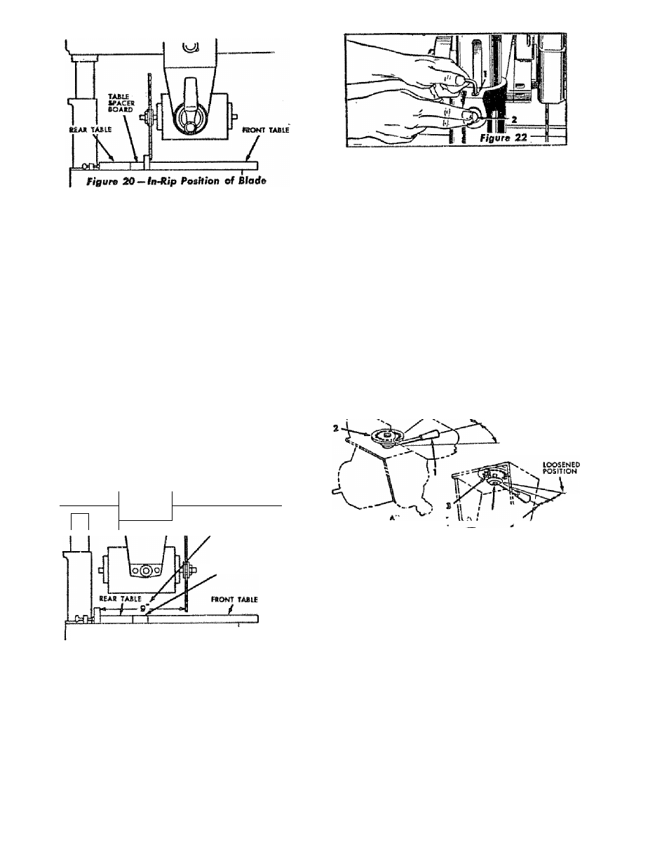
When the fence is In Hs normal posIHon (nest to the front
teble), index the yohe 90° from the cre»*-cwl position so
that the blade b between the motor and the fence, lock
the yoke.
Move the motor »long the radio! arm until the blade, when
spun by hand, ¡wst fewchet the front face of the fence (See
figure 20). The indicator (Item 8, figure 19) on the 'Tn-Rip"
scale should now read 0. If not, shift the position of the indi
cator to read 0.
The same indicator should also reod correctly on the “Out-
Rip" scale when the blade is in the out-rip poitHon. This
indicator should b@ reset with any blade chonge.
The "Out-Rip" scale on the left side of the radial arm is
only used when the fence b in Its extreme reor position
against the table clamps and the blode b in the out-rip
position. The same method of adjustment b used for this
cole indicator except that the blode b positioned os shown
so that 9” b measured between the fence and the nearest
blade tooth. (See figure 21).
The indicotor should then be odfuited to rood 9" on the
"Out-Rip" scale on the left side of the radiol arm.
1
r~1----------------
MEASURE FROM FENCE
_ TO N£AREST BLAßE
TASLI SPACES SOASD
figure 31 — Out-Rip Position of Blatfe
ADJUSTMENTS TO
COMPENSATE FOR WEAR
Even though the finest moterloU ond precision workmonship
have been used to minimixe weor tt b reasonable to experf
some wear. Adjuftmenls hove been built Into your Crofts-
mon saw to reduce or eliminate dib wear.
COLUMN TUBE
KEY
ADJUSTMENT
T excessive radial arm movement b noticed even though
ihe arm is locked in position, dieck the fit of the column
tube key (Item 2, figure 22) ond the keyway in the column
tube.
1. Adjust by loosening the socket set screw (Item 1, figure
22), using the 7/16 hex “I" wrench.
2. Press vigorously against the rear of the column hrise key
(Item 2, figure 14) or C-cJomp the key white slightly
rocking the radial arm back and forth. Thb causes the
key to seot properly in the keyway.
3. Tighten the set screw (Item 1, figure 22) securely while
maintoinirtg pressure on the key.
YOKE ClAMP HANDLE ADJUSTMENT
The normal locking position of the yoke damp handle (item
1, View A, figure 23) is midway between the two sides of
the yoke.
When the handle strikes the yoke before locking, the handle
may be odjusted as feilowst
1. Remove saw guard and blode.
2. Set yoke clamp handle to Position A, figure 23. (Mid
woy.)
3. Remove lock screw (Item 3).
4. With off-set screw driver tom slotted end of the yoke
clomp (Item 2) counterclockwise until
a
slight snugness
of the yoke clomp hondle is felt ot Position A, Figure 23.
^
POSmON DUE TO WEAR
NORMAL tOOHNS
POSITION
LOOSENED POSITION
VIEW
POSITION A
NORMAL tOCKiNS POSITION
^ 2 L
figure 23
5.
To replace lock screw olign holes in yoke clomp with
hole in yoke by a slight adjustment of yoke clamp using
off-set screw driver. Insert lock screw ond tighten.
CARRIAGE
To test for looseness in the corrioge, firmly grasp the car
riage (Item 1, figure 24) ot the level of the ball races and
apply a firm rocking motion.
NoKceoble looseness moy be adjusted as follows:
1. Remove sow guord and blade.
2. Place block of wood on table under motor and torn
elevation crank until weight of motor just rests on block.
3. Remove carriage lock knob assembly (Item 2, figure 24)
and earrioge cover (Item 3, figure 24).
4. loosen 3 hex head machine screws (item 1, figure 25),
eccentric hold-down screw (Item 2, figure 25) ond two
odjusting set screv« in the holes on the side of the car
riage (Items 5, figure 25). Use 1/8 hex "I" wench on
set screws.
5. Rotate eccentric bushing (Item 3, figure 25) clockwise to
obtoin snug fit. The ball retainer (Item 4, figure 25)
should be guided at both ends by hond to prevent
cocking.
12