Assemblimg-adjusting – Sears 113.29003 User Manual
Page 7
Attention! The text in this document has been recognized automatically. To view the original document, you can use the "Original mode".
instrycfions for Assembiirig «nd Operating Year Sow
НОТЕ; WHEN ORDESING REPAtR PARTS
REFER TO PARTS UST FOR COR
RECT PART NUMBER-
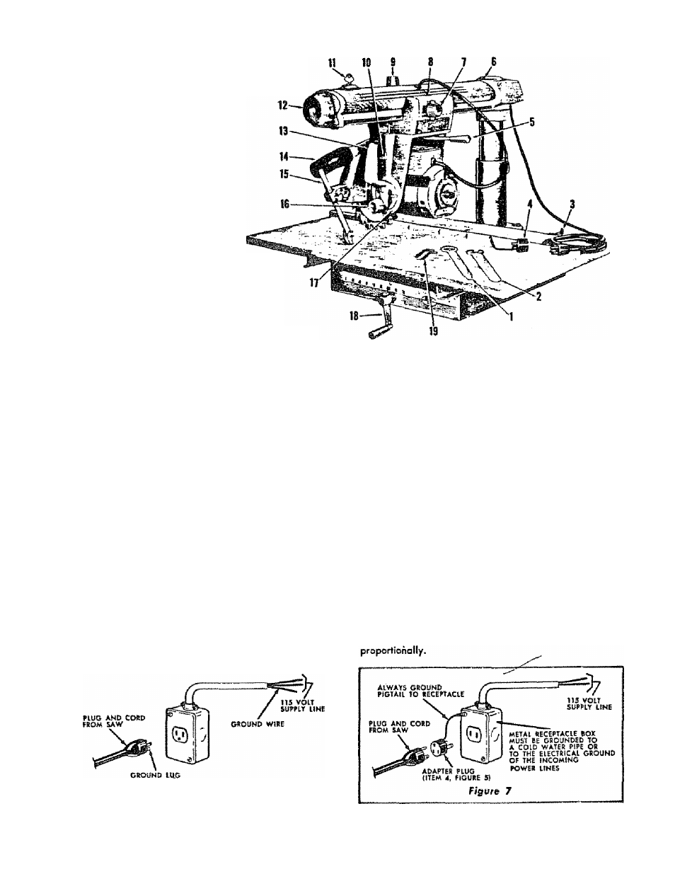
1. Arbor Wrench
2. Shaft Wrench
3. Table Clamp
4. Adapter Plug
5. Yoke Clamp Handle
6. Radial Arm Indicator
7. Carriage Lock Knob
8. Rip Scole Indicator
9. Swivel Latch Pin Rnob
10. Latch Pin Handle
11. Switch Key
12. Arm Latch Handle
13. Bevel Index Handle
14. Discharge Elbow
15. Anti Kick Bock Pawl Assembly
16. Bevel Lock Knob
17. Bevel index Scale and Indicator
18. Elevotion Crank
19. Hex **L" Wrenches
Figure S
ASSEMBLIMG-ADJUSTING
CONNECTING THE MOTOR TO THE POWER SUPPLY
Motor Specifications
115/230 volt, 10/5 amps, 3450 RPM, 60 cycle, olternofing
current (A.C. only) single phase, non-reversible. Rototion:
clockwise viewing saw blade end of motor shaft.
The motor as shipped
is connected
for
115
volts.
For 115
volt operation see Figures 6 and
7
for connecting plug
end cord from saw into 115 volt receptacle.
Safety Preeairfion
The saw motor is equipped with o monuol reset, thermal
overload protector. If during operation this protector opens
the line, immediately turn the switch ”OfT'. The protector
con be closed ogain after the motor has cooled by firmly
pushing the red button on the capacitor cover until the
protector snaps Info the running position. Do not top or
strike the reset button. This protector is not intended to
take the piece of
a
fuse as the protector will not provide
protection against overloads or short circuits in the tines
leading to the motor.
The motor should not be
operated on
a
load
which causes
the
profecforfo open the
line frequently.
For circuit protection use
a
"Fustat" or "Foselron" fuse
—15 ampere fuse for 115 volt operation ond
7Vi
am
pere fuse for 230 volt operation.
For 230 volt operation, see connecting instructions on motor
nomeplate. Also see the '"Worning label" on the rear of
the saw base.
"IMPORTANT" The following wire sizes ore recommended
for connecting the motor to o power source far TROUBLE
PRIE OPERATION.
{UmgtH of
Conductor
Wire Siili ItGqMÌrod
{Am«ricttn Wire
No-)
115 Volt Lines
50 feet or less
100 feet or less
100 feet to 150 feet
150 feet to 200 feet
200 feet to 400 feet
No,
No.
No.
No.
No.
12
10
8
6
4
230 Volf lines
50 feet
or less
No, 14
100 feet
or less
No. 12
100 feet
to 150 feat
No. 10
150 feet
to 200 feet
No. 8
200 feet
to 400 feet
No. 6
For circuits of greater length the wire size must be increosed
Figure
6