Sears 113.29003 User Manual
Page 8
Attention! The text in this document has been recognized automatically. To view the original document, you can use the "Original mode".
MOUNTING THE SAW TO A WORK 8ENCH
The saw should be placed on o suitable sturdy worfc bench
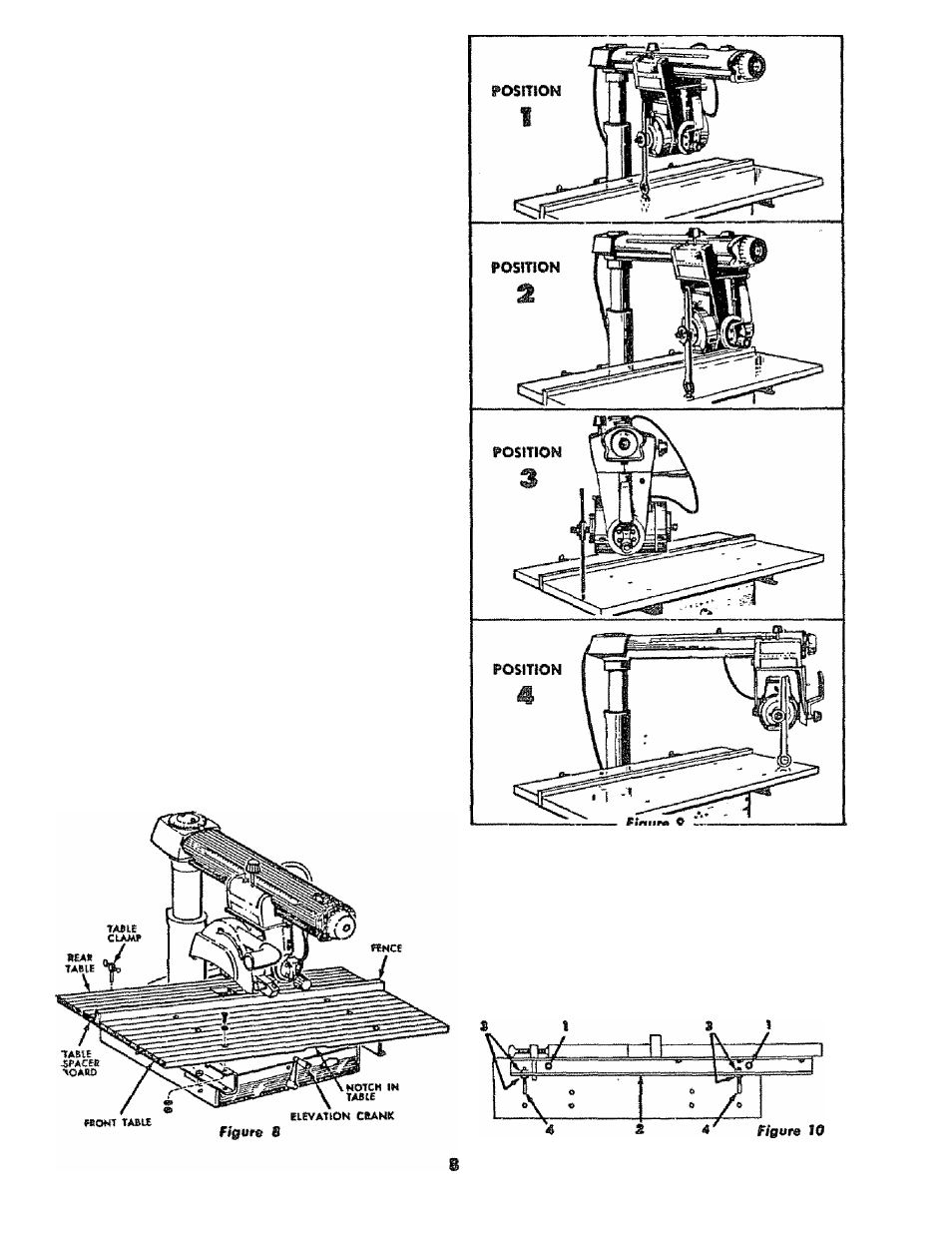
and positioned so that the elevation cranfc {figure 8) is free
to rotate. The base of the sow must be mounted to a fiat
oirfoce on the work bench to prevent distortion of the saw
ose. The nuts, strews, and washers which attach the wooden
shipping skids to the sow base may be used to »ecwè the
saw base to the work bench. Check that taw « level or
sloped slightly to the rear so that carriage when undamped,
does not run freely to the front end of the radial arm.
INSTALLATION OF THE TA8LE AND FENCE
1. Turn elevation crank to raise motor clear of shipping
brackets,
2. Remove shipping brockets from base.
3. Place front table on chonnels with notch In table for
ward and down as shown in Figure 8,
4. Align holes in front table with three forward mount
ing holes in chanriels. See Figure 8.
5. Assemble six mochine screws and washers through six
holes as drown,
6. Attach six lockwashers and nuts. Before tightening nuts
securely push table evenly toward reor of saw. Tighten
nuts.
7. lay fence in verticol position behind front table.
8. Lay table spocer board behind fence.
9. loy rear table with cut-out section forward behind table
spacer boord.
TO. Install table damps as shown and tighten securely
against edge of rear table.
ADJUSTING THE TABLE PARALLEL TO THE
RADIAL ARM
1. Remove sow guard with holding wosher and wing nut.
2. Remove sboft nut arid one loose collar on motor shoft.
See Figure 11.
. Insert arbor wrench between collars on motor draft. See
Figure 9. Tighten shoft nut by bond,
4. Tighten rodiol orm handle (Item Ì2, figure 5).
5.
Loosen carriage lock knob {item
7,
figure 5) and turn
elevation cronk until end of arbor wrench
just
touches
the table top thus permitting the wrench to be swung
bock and forth.
See Position 1, Figure 9. Mark this spot
0od Positions 2, 3 and 4 with
a
pencil,
note
Do not turn the elevotion crank throughout the re
mainder of this procedure as the radial arm must
remoin at the some height obove the table while
checking ot Positions 1, 2, 3 end 4 of Figure 9.
Figure
9
6.
Pull motor to Position 2. Wrench when moved bock and
forth should just contact table tap as in step 4.
7.
Tom arm latch handle (Item 12, figure 5} counterclock
wise and pull out. Move arm to Position 3 of Figure 9»
Tighten radial arm handle end repeat procedure of
step 6.
*
6. Move rodial arm to Position 4 of Figure 9, tighten radial
arm handle and repeot above procedure.
If contact between the wrench and the table tap Is not the
same of oil four positions the table con be leveled as fol
lows: (See Figure 10}.