Carrier 38VH User Manual
Page 5
Attention! The text in this document has been recognized automatically. To view the original document, you can use the "Original mode".
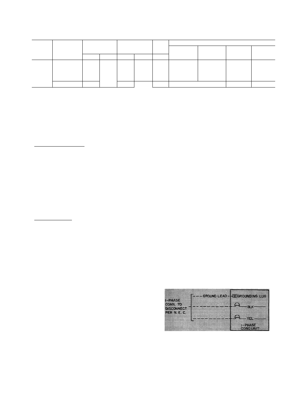
Table 5 — Electrical Data
COND
UNIT
38VH
V/PH
OPER
VOLTS*
COMPR
FAN
BRANCH CIRCUIT
Min Wire
Sizet
(AWG)
Max Ft
Wiref
Min Gnd
Wire
Size
Fuse
Ampsj;
Max
Min
LRA
RLA
FLA
001
40 6
6 9
9
14
37
sa
12
15
002
49 0
103
9
14
12
26
41
12
25
003
208-230/1
253
197
69.0
154
9
12
28
44
10
35
004
83 5
17 9
1 2
10
a
38
S9
8
40
045
88.0
17.1
1.2
10
s
39
a?
8
35
005
230/1
253
207
97 0
22 4
2 3
10
8
32
-
*
8
50
f
Corresponding wire sizes and wire lengths
FLA — Full Load Amps
LRA — Locked Rotor Amps
RLA — Rated Load Amps
’Permissible limits of the voltage range at which the unit will operate
satisfactorily
tCopper wire sizes and lengths
ifMaximum dual element size
NOTE Control circuit is 24-v on all units and requires externa I power source
Mechanical Connection — (Mate one set of con
nections at a time.)
1. Loosen nut on Compatible Fitting one turn.
Do not remove.
2. Remove plug and be sure O-ring is in the
groove inside the Compatible Fitting.
3. Cut tubing to correct length, deburr and size
as necessary.
4. Insert tube into Compatible Fitting until it
“bottoms.” Tighten nut until it bottoms on
back coupling flange. Keep tube bottomed in
Compatible Fitting while tightening nut.
Sweat Connection — (Use refrigerant grade tubing.)
1.
Remove locking nut, rubber O-ring and
Schraeder core and cap from valve service port.
2. Cut tubing to correct length, deburr and size
as necessary.
3.
Insert tube in Compatible Fitting until it
“bottoms.” Wrap top and bottom of service
valves in wet cloth to prevent damage by heat.
Solder with low-temperature (450 F) silver
alloy solder.
4. Replace Schraeder core and cap.
5. Evacuate or purge system using field-supplied
refrigerant.
Step 3 — Make Electrical Connections
— Be
sure field wiring complies with local and national
fire, safety and electrical codes, and that voltage
to unit is within limits shown in Table 5. Contact
local power company, for correction of improper
line voltage.
See Table 5 for recommended wire and fuse sizes.
When making electric connections, provide clear
ance at unit for refrigerant piping connections.
INSTALL A BRANCH CIRCUIT DISCONNECT
PER N.E.C. of adequate size to handle unit starting
current. Locate disconnect within sight of and
readily accessible to the unit, per section 440-14 of
National Electrical Code (NEC).
ROUTE LINE POWER LEADS INTO UNIT —
Extend leads from disconnect thru hole provided
in basepan (Fig. 1) and into unit junction box.
CONNECT GROUND LEAD AND POWER
WIRING — Connect ground lead to a ground lug in
control box for safety. Then connect power
wiring. See Fig. 4. Splice line power leads to yellow
and black pigtails. Use wire nuts and tape at each
connection.
Opersíío» of isail on improper Uise voltage
coasnstutes al>ííse and coaid aHect
C&tei&i:
Wsrranty. See Table 5, Do noi apply unit
m
sysiens wliem voltage may fluctiiate above or
Splice Connections
______Field Wiring
______ Factory Wiring
Fig. 4 — Line Power Connections