Table 4 — accessories – Carrier 38VH User Manual
Page 4
Attention! The text in this document has been recognized automatically. To view the original document, you can use the "Original mode".
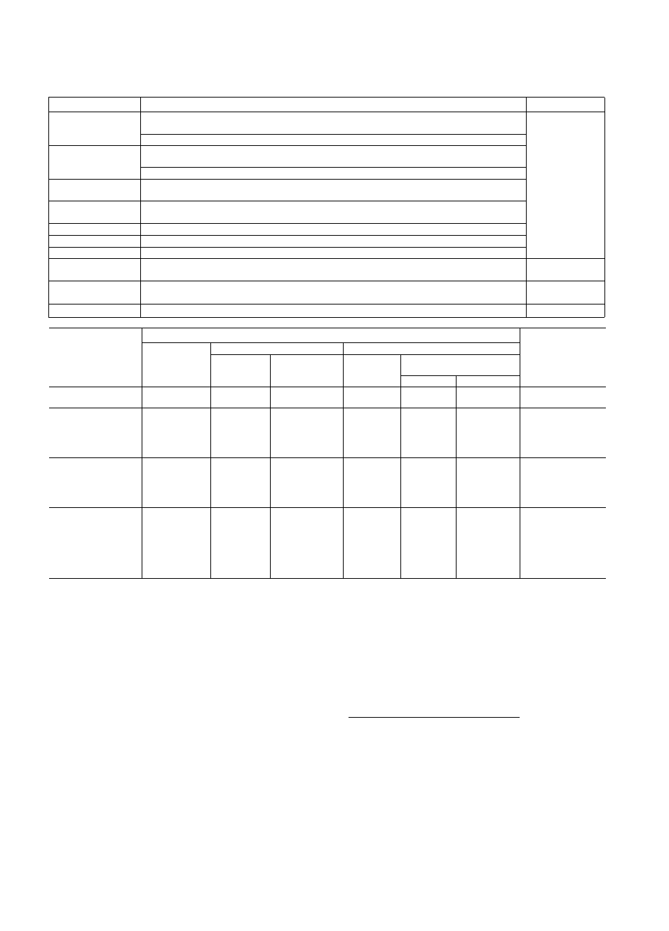
Table 4 — Accessories
PART NO.
DESCRIPTION
UNIT
HH01AD040
HH93AZ040
HH51AR001
Low-Voltage Control — Floneywell Deluxe Thermostat
Thermostat Subbase
All
Comfort Control Center (Use with FIFI01AD040)
HH07AT070
HH07AT074
HH93AZ076
Low-Voltage Control — Honeywell Thermostat
Thermostat Subbase (with Automatic Changeover)
HH01AD042
HH93AZ042
Low-Voltage Control — Honeywell Thermostat
Thermostat Subbase
HH01YA092
HH93YZ094
Low-Voltage Control — Grayson Thermostat
Thermostat Subbase
38GS900102
Indoor Fan Relay (Six HN61KJ210)
38GS900212
Low-Voltage Transformer (Six 38GS900091)
38HQ900011
Hot Shot — domestic water pre-heater
38UE900001
Chillermate refrigerant-to-water heat exchanger
38VH003,004,
045,005
32LT900301
Motormaster® Head Pressure Control Special field-installed fan motor HC42VE233 required
38VH002,003,004,
045,005
38GS900321
Liquid Line Filter-Drier (Six 38GS900332)
All
C
TUBING
PACKAGES
TUBING*
UNIT
Length
(ft)
Liquid
Suctionf
OD
(in )
Tube End
OD (in.)
OD
(in.)
Tube End,
OD (in.)
Evap
Cond
38LS958151
15
3/8
3/8
5/8
3/4t
5/8
38VH001
38LS958201
20
3/8
3/8
5/8
3/4t
5/8
38VH002
38LS958251
25
3/8
3/8
5/8
3/4t
5/8
38LS958301
30
5/16
3/8
5/8
3/4J
5/8
38LS958351
35
5/16
3/8
5/8
3/4i
5/8
38VH001
38LS958401
40
5/16
3/8
5/8
3/4i
5/8
38LS958501
50
1/4
3/8
5/8
3/4i
5/8
38LS934251
25
3/8
3/8
3/4
3/4
3/4
38LS934301
30
3/8
3/8
3/4
3/4
3/4
38LS934351
35
3/8
3/8
3/4
3/4
3/4
38VH002
38LS934401
40
3/8
3/8
3/4
3/4
3/4
38LS934501
50
3/8
3/8
3/4
3/4
3/4
38LS978151
15
3/8
3/8
7/8
3/4
3/4
38VH003
38LS978201
20
3/8
3/8
7/8
3/4
3/4
38VH004
38LS978251
25
3/8
3/8
7/8
3/4
3/4
38VH045
38LS978301
30
3/8
3/8
7/8
3/4
3/4
38VH005
38LS978351
35
3/8
3/8
7/8
3/4
3/4
38LS978401
40
3/8
3/8
7/8
3/4
3/4
(See Note 2)
38LS978501
50
3/8
3/8
7/8
3/4
3/4
*For maximum capacities, use suction line sizes recommended in
Table 3 If accessory tubing package is used on 38VH004,045,
005 units, a reduction in capacity can result Field-supplied
1-1/8 in suction line is recommended with all 28VFI coil
installations
fSuction line is insulated and has a 90 degree bend at one end
JFor 5/8-in evaporator connection, cut off 3/4-in end
NOTE Do not cut 3/8-in OD liquid lines to a length shorter than
10 feet Do not cut 5/16-or 1/4-in liquid line Do not cut 7/8-in
OD suction lines
Do not use damaged or contaminated tubing.
Always evacuate or purge evaporator coil and
tubing system. When purging, use field-supplied
refrigerant, not unit holding charge refrigerant.
When making tubing connections, be sure to pro
vide clearance at unit for electrical connections.
REPLACE THE ACCURATER™ REFRIGER
ANT CONTROL PISTON IN THE INDOOR
COIL, if required, before connecting refrigerant
lines. See Carrier Cooling System Optimization,
page 2.
CONNECT REFRIGERANT LINES to fittings on
condensing unit suction and liquid service valves
(Fig. 1). Unit Compatible Fittings permit mechani
cal (quick connect) or sweat connections.
Models 38VH002,003,004,045,005 — When using
1-1/8 in. field-supplied suction line, remove suction
line adapter taped to compressor suction line. Sweat
connect refrigerant suction line to 1-1/8 in. end of
adapter. Be sure to provide a heat sink at the service
valve to prevent damage during sweating operation.
Connect 3/4-in. end of adapter to unit suction line
Compatible Fitting. Connect liquid refrigerant line
to unit. When a 7/8-in. field-supplied suction line
is used, provide a field-supplied 3/4-in. to 7/8-in.
suction line adapter. (Not necessary if 38LS acces
sory tubing is used.)