Table 3 — field-supplied tubing data, Step 2 — make tubing connections, Fig. 3 — refrigerant line hangers – Carrier 38VH User Manual
Page 3
Attention! The text in this document has been recognized automatically. To view the original document, you can use the "Original mode".
Condensing Units Connected to Non-Carrier Evap
orators — Check refrigerant charge when the con
densing unit is added to a system in which other than
a Carrier-approved evaporator is to be used or
where the evaporator has been previously installed.
Check that field-supplied refrigerant piping is in
accordance with refrigerant piping data (Table 3).
Step 2 — Make Tubing Connections
— Con
densing units may be connected to evaporator sec
tions using Carrier accessory tubing package or
field-supplied tubing of refrigerant grade. See Table
4 for accessory tubing sizes. Table 3 for recom
mended field-supplied tubing sizes.
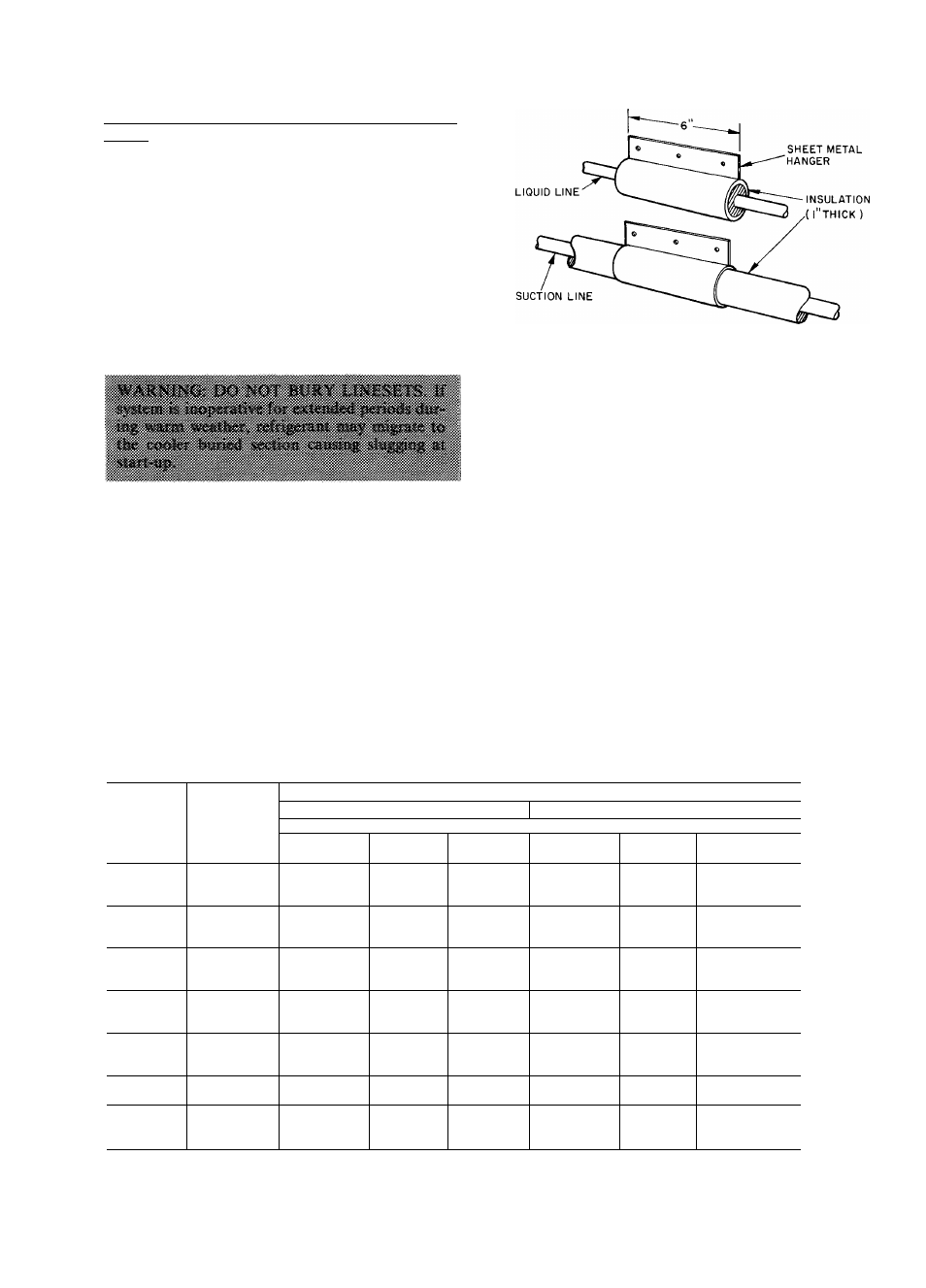
Isolate interconnecting tubing from framing and
ductwork or where tubing runs thru stud spaces,
enclosed ceilings or pipe chases. Use isolation type
hanger (Fig. 3) since rigid fastening transmits pulsa
tions to structure creating objectionable sound.
A capacity and efficiency reduction results if
undersized Carrier accessory tubing is used in 38VH
systems. (Example: When a 25-ft accessory tubing
Fig. 3 — Refrigerant Line Hangers
package is used on a 38VH004 system, the smaller
suction line will result in a capacity reduction of 3%.)
For maximum capacity and efficiency from this sys
tem, use suction line recommended in Table 3.
Length of interconnecting tubing may necessitate
refrigerant charge adjustment. Follow special re
quirements described in Initial Start-Up, Refrig
erant Charging. Do not use less than 10 ft of inter
connecting tubing. On Carrier accessory tubing
packages, do not cut 5/16-in. or 1 / 4-in. liquid line or
7/8-in. suction line. These tubing packages have
swaged ends. If swage at end of tubing is cut off, the
tubing will not fit into unit refrigerant line fittings.
Bend or coil excess tubing to fit.
Table 3 — Field-Supplied Tubing Data
NOTES
1 Maximum allowable vertical separation for evaporator over the
condensing unit is 50 feet
2 Over 50-ft vertical separation, the condensing unit must be
located above evaporator
3 The maximum total tubing length between units is 150 feet
4 All suction tubing must be insulated with 3/8-in thick, flexible
foam tubing (Armaflex 22 or equivalent)
5 Piston numbers effective December 1, 1979
Vertical separation from 51 to 100 feet (Condensing unit
iabove evaporator)
CONO
UNIT
38VH
EVAP
SIZE
REFRIGERANT LINE LENGTH (ft)
10 to 50 ft
51 to 150 ft
Line Diameter
Suction
(in.)
Liquid
(in.)
Indoor
Piston*
Suction
(in.)
Liquid
(in.)
Indoor
Piston*
018
5/8
3/8
52
3/4
5/16
52 ^
001
024
5/8
3/8
52
3/4
5/16
52 ■
030
5/8
3/8
TXV
3/4
5/16
TXV ■
024
7/8
3/8
57
7/8
5/16
57 ■
002
030
7/8
3/8
59
7/8
5/16
59 ■
036
7/8
3/8
TXV
7/8
5/16
TXV ■
030
7/8
3/8
63
1-1/8
5/16
63 ■
003
036
7/8
3/8
65
1-1/8
5/16
65 ■
042
7/8
3/8
TXV
1-1/8
5/16
TXV ■
036
1-1/8
3/8
76
1-1/8
5/16
76 U.
004
042
1-1/8
3/8
78
1-1/8
5/16
78 ■
048
1-1/8
3/8
TXV
1-1/8
5/16
TXV ■
042
1-1/8
3/8
76
1-1/8
3/8
76 ■
045
048
1-1/8
3/8
78
1-1/8
3/8
78 m.
060
1-1/8
3/8
TXV
1-1/8
3/8
TXV »
nriR
048
1-1/8
3/8
82
1-1/8
3/8
82 ■
060
1-1/8
3/8
84
1-1/8
3/8
84 fm
002
28VH002
1-1/8
3/8
63
1-1/8
5/16
63 W
003
28VH004
1-1/8
3/8
70
1-1/8
5/16
70 W
004
28VH004
1-1/8
3/8
78
1-1/8
5/16
78 B
*At 95 F outdoor air design temperature At other design temperatures, piston sizes may vary See Table 2