Carrier 38VH User Manual
Air-cooled condensing units
Attention! The text in this document has been recognized automatically. To view the original document, you can use the "Original mode".
Number One
AirCorditbninq
Maker
Division of
Carrier Corporation
Carrier Parkway • Syracus
N Y 13221
Air-Cooled Condensing Units
INDEX
Page
SAFETY CONSIDERATIONS........................... 1
INSTALLATION
Step 1 — Check Equipment and Jobsite.... 2,3
• UNPACKAGE UNIT
• INSPECT EQUIPMENT
• COMPLETE OR CONSIDER SYSTEM
REQUIREMENTS
Step 2 — Make Tubing Connections ............... 3-5
• REPLACE THE ACCURATER™
REFRIGERANT CONTRQL PISTON IN
THE INDOOR COIL
• CONNECT REFRIGERANT LINES
Step 3 — Make Electrical Connections........... 5,6
• INSTALL A BRANCH CIRCUIT
DISCONNECT PER N.E.C.
• ROUTE LINE POWER LEADS INTO UNIT
• CONNECT GROUND LEAD AND
POWER WIRING
• CONNECT CONTROL POWER
WIRING (24 v)
START-UP................................................................ 6
SERVICE.................................................................. 9-II
MAINTENANCE.................................................. I I - I 2
SAFETY CONSIDERATIONS
Installation and servicing of air conditioning
equipment can be hazardous due to system pres
sure and electrical components. Only trained
and qualified service personnel should install,
repair or service air conditioning equipment.
Untrained personnel can perform basic main
tenance functions of cleaning coils and cleaning
and replacing filters. All other operations should bci
performed by trained service personnel. When
working on air conditioning equipment, observe
precautions in the literature, tags and labels
attached to the unit and other safety precautions
that may apply.
Follow all safety codes. Wear safety glasses and
work gloves. Use quenching cloth for brazing
operations. Have fire extinguisher available for all
brazing operations.
WARNING; Before performing service or
maioienance oj^erairon^ on system, turn off
m^n power switch to iadoor mut and
out
door
UJI&. Tui» off accessory heater power
switch
if
applicable.
Eleetrical
shock
could
cause
persoii^
injury.
ik
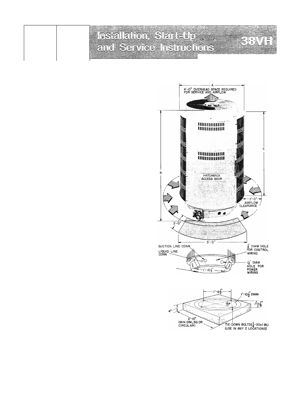
-If MTG
SLOTS(USE ANY
2)
C=3 SPACE REQUIRED FOR SERVICE
^ CONDENSER AIRFLOW
CONCRETE MOUNTING PAD^ISQUARE OR CIRCULAR)
^CONCRETE PAD SHOULD WEIGH |-f TO 2 TIMES WEIGHT OF UNIT
Certified dimension drawings available on request
Fig. 1 — Dimensions, Connections and
Mounting Pad
© Carrier Corporation 1980
Form 38VH-2SI
Document Outline
- Air-Cooled Condensing Units
- INSTALLATION
- Table 3 — Field-Supplied Tubing Data
- START-UP
- CAHTIONt To
- Do not overcharge sysicio. Aa overcharge
- Table 8 — Chargemaster Charging Chart (Non TXV Systems)t
- SERVICE
- Unit Controls and Safety Devices
- Compatible Fitting Repair
- Condenser Fan Motor Removal
- MAINTENANCE
- Lubrication
- TROUBLESHOOTING GUIDE
- SYMPTOM AND PROBABLE CAUSE
- COMPRESSOR SHUTS OFF, FAN OVERLOAD
- OR HIGH PRESSURE SWITCH CUT OUT, OR
- INTERNAL PRESSURE RELIEF OPENS
- COMPRESSOR RUNS BUT COOLING IS INSUFFICIENT
- High Suction Pressure
- PROBABLE REMEDY
- COMPRESSOR SHUTS OFF FROM LOW-PRESSURE SWITCH CUTOUT
- Evaporator Fan Stopped
- COMPRESSOR SHUTS OFF,
- WILL NOT RESTART
- Contactor Closed or Closes Then Opens