Unit controls and safety devices, Compatible fitting repair – Carrier 38VH User Manual
Page 10
Attention! The text in this document has been recognized automatically. To view the original document, you can use the "Original mode".
12. Triple-evacuate system. Recharge system as
described previously.
Filter-Drier
— Install field-supplied filter-drier
(Table 4) in system liquid line when refrigerant
system is opened for service as described under
Compressor Removal. Position drier in liquid line
at convenient location.
Pumpdown Procedure
— The system may be
pumped down in order to make repairs on low side
without losing complete refrigerant charge.
1. Attach pressure gage to suction service valve
gage port.
2. Frontseat the liquid line valve.
3. Start unit and run until suction pressure reaches
5 psig (see Caution).
4. Shut unit off and frontseat suction valve.
5. Vent remaining pressure to atmosphere.
Unit Controls and Safety Devices
HIGH-PRESSURE
RELIEF
VALVE,
when
equipped, is located in compressor. Relief valve
opens if system operating pressure differential
between suction and discharge pressure reaches
500 psi on all models.
HIGH-PRESSURE SWITCH is located on unit
liquid line. High-pressure switch settings are: cut
out, 425 ± 5 psig; cut-in, 320 ± 20 psig.
LOW-PRESSURE SWITCH is located on unit suc
tion line. Low-pressure switch settings are: cutout,
31 ± 4 psig; cut-in, 60 (+15, -0) psig.
INTERNAL TEMPERATURE AND/OR CUR
RENT SENSITIVE OVERLOADS reset auto
matically when motor internal temperatures drop
to a safe level (overload may require up to 30 min
utes to reset). When internal overload is suspected
of being open, check by using an ohmmeter or
continuity tester. If necessary, refer to Carrier
Standard Service Techniques Manual, Chapter 2,
Electrical, for complete instructions.
INHERENT FAN MOTOR PROTECTION —
Protects
motor
from
abnormal
current
and
temperature.
SOLID STATE TIME GUARD® CIRCUIT pro
tects unit compressor by preventing short cycling.
Time Guard provides a 5 ± 2-minute delay before
restarting compressor after shutdown for any
reason. On normal start-up, the 5-minute delay
occurs before thermostat closes. After thermostat
closes, the Time Guard then provides a 3-second
delay to prevent contactor chattering.
CRANKCASE
HEATER
SWITCH
^
The
purpose of the heater is to keep the crankcase
warm during the off cycle and thus prevent dilution
of the oil with refrigerant. This assures good lubri
cation and prevents loss of oil from erankcase
during start-up. Switch closes (activates) at 65 F on
coil temperature drop. Opens (deactivates) at 85 F
on coil temperature rise.
Fig.
Repair of Mechanical Connection
Compatible Fitting Repair
MECHANICAL CONNECTION — Frontseat unit
service valves. Relieve refrigerant pressure from
tubing. Back off locknut from Compatible Fitting
onto tube. Cut fitting between threads and seal
ring head as shown in Fig. 8. Remove tubing section
remaining in threaded portion of fitting. Discard
locknut.
Clean, flux, and insert new tube end into remain
ing portion of Compatible Fitting. fVrap valve base
in wet rag. Heat and apply low-temperature (450 F)
solder.
SWEAT CONNECTION — Frontseat unit service
valves. Relieve refrigerant pressure from tubing.
Clean and flux area around leak. Repair using low-
temperature (450 F) solder.
Evacuate or purge evaporator coil and tubing
system. Add refrigerant charge. See Refrigerant
Charging instructions described previously.
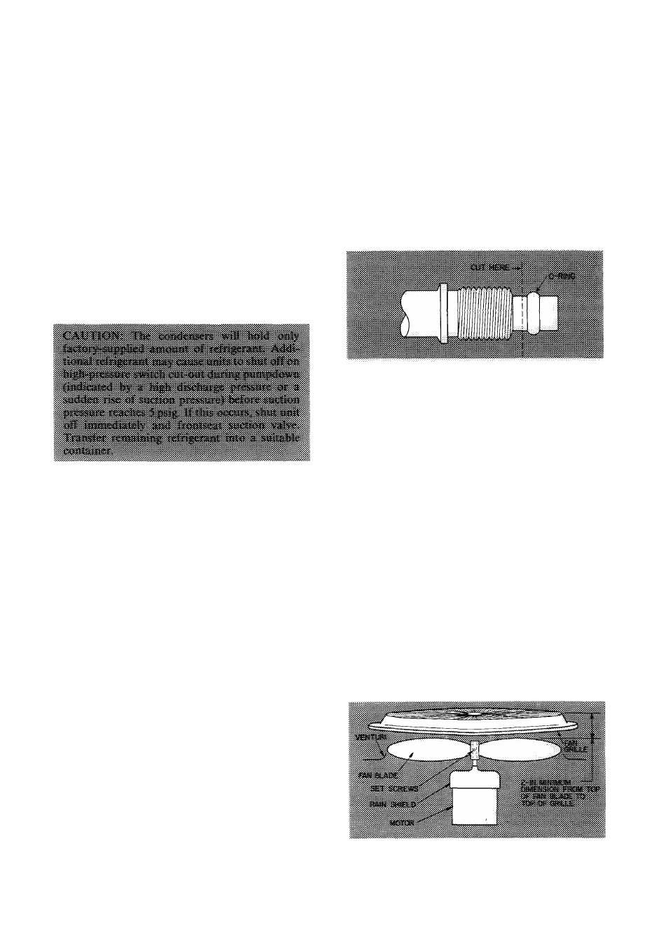
Condenser Fan Adjustment
— Required fan
position is shown in Fig. 9. Adjust fan by loosening
setscrew(s) and moving fan blades up or down.
Fig. 9 — Condenser Fan Position
10