Fig. 9 — field control thermostat wiring – Carrier 50EQ User Manual
Page 6
Attention! The text in this document has been recognized automatically. To view the original document, you can use the "Original mode".
10. Reset thermostat at a setting above room tem
perature. Compressor(s) will shut off.
TO SHUT OFF UNIT — Set system selector switch
at OFF position or reset thermostat at a setting
above room temperature.
Do not shut off unit circuit breakers except when
unit is to be serviced. Crankcase heaters are ener
gized only when unit power is on.
Units are equipped with Signal-LOC™ compres
sor protective device. Unit shuts down on trip of any
safety device and indicator light on thermostat
comes on. Check reason for safety device trip. Com
pressor restart is accomplished by manual reset at
room thermostat by moving selector switch to OFF
and then ON.
Heating
— To start unit, turn on main power
supply. Refer to Crankcase Heaters.
Set thermostat at HEAT, fan at AUTO, and a
setting above room temperature.
First stage of the heating thermostat energizes
compressor no. 1; the second stage energizes com
pressor no. 2. The electric heater elements are not
energized until the field adjustable outdoor air ther
mostat closes. When this occurs, the first stage of the
thermostat energizes compressor no. 1 and no. 2;
the second stage energizes the electric heater
elements.
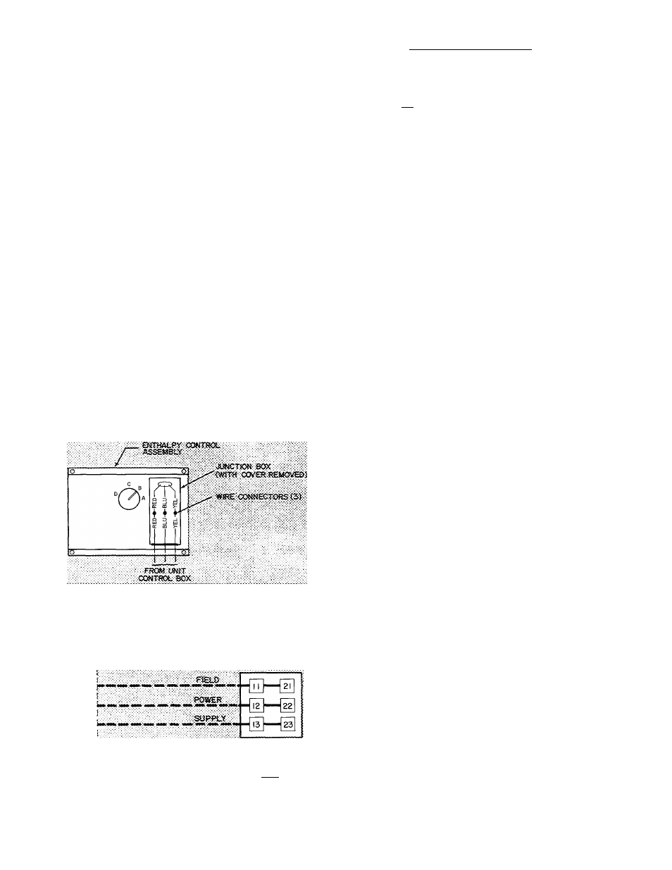
Fig. 7 — Enthalpy Control Assembly
Wiring Connections
T8t
o u;
CO Q,
««—I |0|
EQUIP GKO
Fig. 8 — Field Power Wiring Connections
REMOVABLE JUMPER
I
r
R-M^
TBEfaaosTATasssMSi-v
1^ ^
^
[c]'-
[S [
b
] ^
И Й1 И И
Й 0
oil Qi] LJii
^ O =i ^
5
z
^
CC C
5 O > CD q. 00 CD g
Fig. 9 — Field Control Thermostat Wiring
Check heating effect at duct supply outlets.
Check unit operation. Referto heating operation
chart in service section.
TO SHUT OFF UNIT — Set system selector switch
at OFF or set heating selector lever below room
temperature.
Safety Relief
— A fusible plug in the accumulator
provides pressure relief under abnormal tempera
ture and pressure conditions.
Defrost Cycle
— As frost builds up on the outdoor
coil, the defrost thermostat closes and the unit
operates in a defrost cycle (controlled by the defrost
timer and thermostat). During this cycle the outdoor
air fan shuts off and the unit operates on cooling
cycle for a maximum of 10 minutes. During defrost,
bottom of outdoor coil defrosts first to ensure
proper drainage.
If only compresor no. 1 is operating at beginning
of a deUost cycle, compressor no. 2 is started to
maintain warm air supply to conditioned space.
If both compressors are operating, one is pre
vented from defrosting as the other compressor con
tinues thru the defrost cycle. The electric heaters are
not automatically energized during a defrost cycle.
Automatic
Changeover
(with
Automatic
Changeover Thermostat only)
— The unit will
automatically switch from heating mode to cooling
mode when the system selector switch is set at
AUTO, and the temperature of the conditioned
space rises to cooling selector lever setting. When
the temperature of the conditioned space falls to the
heating selector lever setting, the unit will auto
matically change from cooling mode to heating
mode.
The thermostat and unit are so connected that
the cooling and heating systems will not operate
simultaneously.
Economizer Operation
— If unit is equipped with
a modulating outdoor air control (economizer), it
should operate as follows:
THERMOSTAT SETTINGS — Set enthalpy con
trol to the desired temperature and relative humidity
which provides cooling with outside air only (no
compressor operation). To determine appropriate
setting of enthalpy control:
1. Determine the maximum combination of relative
humidity and temperature of the supply air con
sidered acceptable for the installation.
t
€