Table 5 — indoor air fan pulley data, Economizer adjustment – Carrier 50EQ User Manual
Page 10
Attention! The text in this document has been recognized automatically. To view the original document, you can use the "Original mode".
Indoor Air Fan Adjustment
— Fixed fan speeds
are shown in Table 1; note that second pulley is
shipped with unit. For other fan speeds, select field-
supplied motor or pulleys from Table 5.
Table 5 — Indoor Air Fan Pulley Data
UNIT
50EQ
FAN
RPM
MOTOR
PULLEY
FAN
PULLEY
No. Grooves - Type - In.
024
028
!
325 ! 2
■■ 33T r
2 -
i 107.3 T.2.
i 1093 t 2■
f 1159 f2-
1 .122.5: . .2 •
I 1300 j 2
'■"“sis
; 985
' T067.
j 1088
! 1153
:
■■ Ì30S
3 V - 5 . 6 ! 2 ■
3V - 6.0 f2 -
3V - 6.5 1
2
:
3V - 5.0 i 2 ■
3V - '5.3
[ 2
•
.3V,t5.6 J2.
3y - 6.0 i 2
3V - 5.6
3V.'6,0
3V - 6.5
3V - 50
3V - 5.3
5.6 ■{
3V-:60
BELT
NO - SIZE
3V-10 6
2
3V-m'5T2’-
3V.- 10..6.T.2 :
3V - 8 0 : 2 -
3V- "8X1 |2-
.3y..-...8..0...{.2.;
3V - 8.0 [ 2 _ -
3V -T0.6"'t 2 -
3V-T0.6'{2’-
3V-10,6
|2-
3V - 8 0 i 2 -
3V - 8.0 ! 2 •
3V- 60 5 2'-
■3V - 9.0 .2 ■
3V - 710
SV'^TSO'
3y..-..790.
3V - 670
3r-'670-
.3v -:mo
3V-J10
3V - 710 '
9V
-750"
'3V.-.750
3V - 670
3V - 670
3^-670.
034
: 925 1 2-
1073 I 2 -
i 1093 I 2 -
i 1159 f 2 -
; 1226 : 2'
i 1300 ; 2
J
3V: - SJS. \
2-
3V - 6.6 1 2 -
3V - 5 0 r 2
f2"
3V - 5.6 I 2 -
3V - 6 0 I 2 ■
3V-10.6 Ì 2
3V - 10,6 12 -
3V - 8.0' i 2"
3V- 8.0" p
3V- 8,0, i 4
3V - 8 0 i '2
3V--750-
3V-750.
■3V-'670
:3V-710
3Y.Ì 710.
3V - 710
Shaded values indicate standard or optional pulley com
binations available as shown in Physical Data table All
other combinations are field supplied
PULLEY REMOVAL — Pulleys are of the fixed
type. To remove, shut off unit power. Loosen fan
motor mounting plate and remove belt. Remove
pulley from shaft.
After reinstalling pulley and belt, check pulley
alignment and belt tension as described below.
PULLEY ALIGNMENT ^ Loosen fan shaft pulley
bushing and slide pulley along shaft. Make angular
adjustment by loosening motor mounting plate and
repositioning it as required.
BELT TENSION — Adjust belt tension by moving
motor back until only a SLIGHT BOW appears in
the belts on the slack side of the drive while running
under full load. Secure motor. Recheck belt tension
after 24 hours of operation, adjust as necessary.
Exhaust Air Fan Adjustment
— Adjust belt ten
sion so that 1/8-in. deflection at 5- to 8-lb pressure
between pulley centers can be obtained. To change
tension, loosen motor mounting bolts, reposition
motor and tighten mounting bolts. Tighten locknut
and bolt under motor mounting plate to secure in
fixed position.
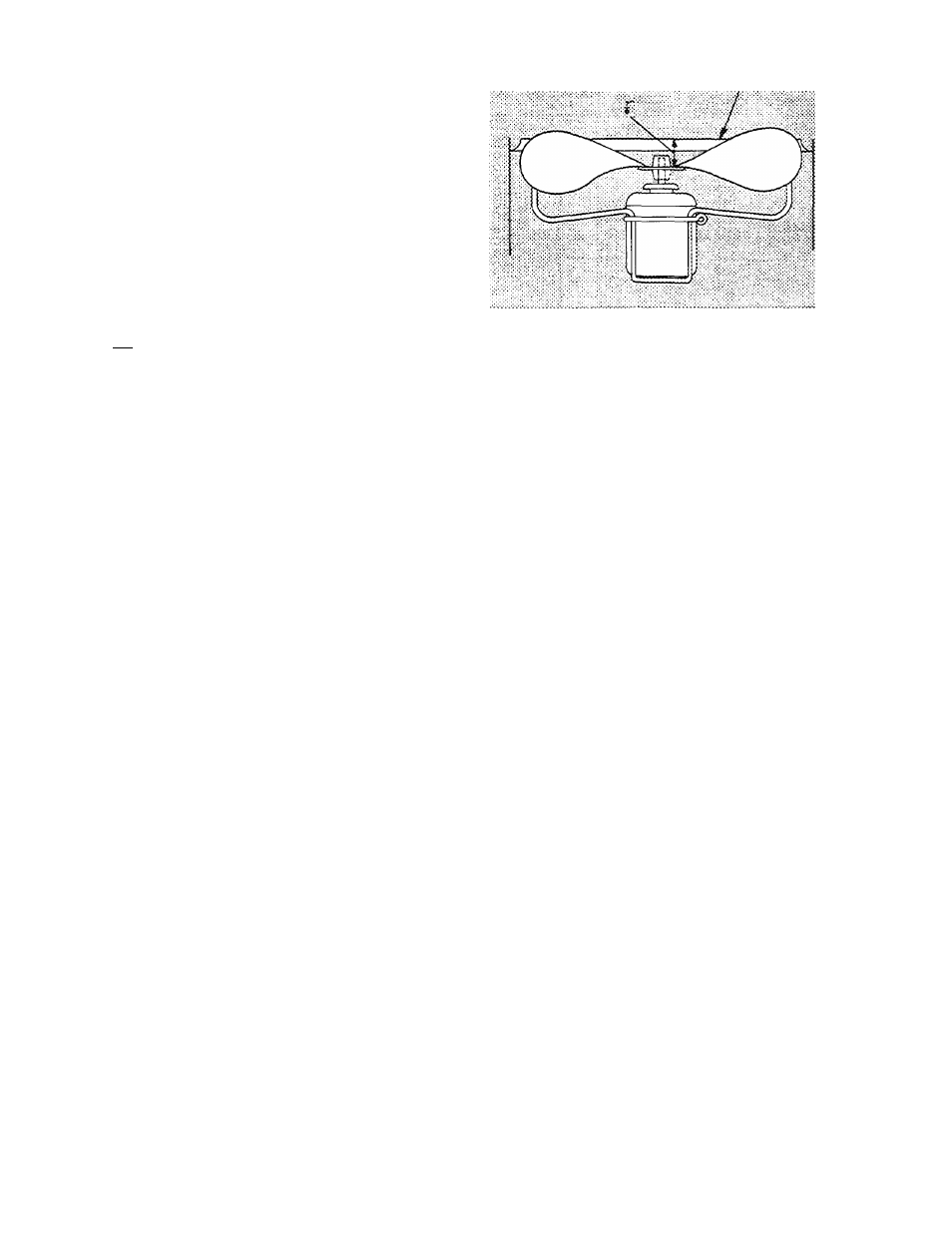
Outdoor Air Fan Adjustment
(Fig. 11) — Shut off
fan power supply. Remove fan guard and loosen fan
hub setscrews. Adjust fan height using a straight
edge laid across fan venturi. Tighten setscrews. Fill
hub recess with permagum to prevent hub from rust
ing to motor shaft.
fiSK OSCIC VEMTUSl
'i .
Fig. 11 — Outdoor Air Fan Adjustment
Economizer Adjustment
1. Set enthalpy control at its highest setting. If out
door temperature is above 70 F, perform the
following: Install jumper between enthalpy con
trol terminals 1 and 2 (red and yellow wires).
Remove control relay (CR) from unit econo
mizer control panel.
2. Set system selector switch at COOL and set
cooling temperature selector lever at lowest
setting.
Cooling mode may also be simulated by remov
ing the thermostat wires from terminals Y1 and
Y2 and installing a jumper between terminals R
and Yl.
3. Set mixed air thermostat at its lowest setting.
Outdoor air damper will go to fully open position
(indoor air damper closes).
4. Set mixed air thermostat at its highest setting.
Outdoor air damper will go to fully closed posi
tion (indoor air damper opens).
5. Adjust mechanical linkage if necessary, for
correct positioning (Fig. 12). If enthalpy control
terminals were jumped and plug-in control relay
was removed from unit control box in step 1,
remove jumper and replace plug-in control relay
after positioning dampers. If cooling mode was
simulated as described in step 2, be sure to re
move jumper and reconnect thermostat wires
to Yl and Y2.
DAMPER VENT POSITION SETTING
1. Set fan switch on thermostat assembly at FAN
(continuous fan operation) and close night
switch (if used).
2. Set thermostat system selector switch at OFF.
3. Remove cap from vent adjustment screw on top
of damper motor terminal box cover.
Turn adjustment screw slowly until dampers
assume desired vent position. Do not manually
operate damper motor. Damage to motor will result.
10