Carrier 50EQ User Manual
Page 2
Attention! The text in this document has been recognized automatically. To view the original document, you can use the "Original mode".
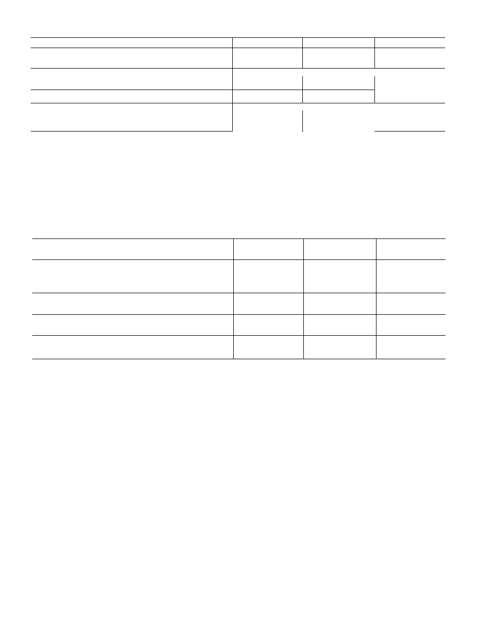
Table 1 — Physical Data
UNIT MODEL
50EQ024
50EQ028
50EQ034
OPERATING WEIGHT (lb)
Base Unit
3300
3900
4550
Base Unit with Economizer
3450
4075
4750
COMPRESSOR
Serviceable, Reciprocating Hermetic
No. .Model
2 06D824
2. 06D328
2 06D537
Oil (3GS or B1) pts (per Compr)
10
10
10
REFRIGERANT CHARGE
R-22
R-22
—
Sys 1*...Sys 2 (lb)
20.0...21.3
23.5..24.0
29.1..29.1
OUTDOOR AIR FANS
Direct Drive, Propeller
No. ...Hp
2 . 1
2 . 1
3 1
Frame (NEMA)
56T
56T
56T
Rpm (1-Phase)
1050
1050
1050
IIMDOOR AIR FANS
Motor
Shaft Diam (in.) — RPM 1750
Motor Frame Size
Motor Pulley Pitch Diam (in.)t
Fan Pulley Pitch Diam (in.)
Fan Speed (rpm)
Fan Shaft Diam (in )
Belt No. ...Size
Std
Opt
Std
Opt
Std
Opt
Std, A,B
Opt, A,B
Std
Opt
Std, A,B
Opt, A,B
Std
Opt
5
7-1/2
1
-
1 / 8
1-3/8
1S4T
213T
6 5 6 0
5 3 5 6
106
8
1073
991
1159 1225
1-3/16
2 3V750
2 3V670
1300
Fixed Speed Centrifugal
7-1/2
10
1-3/8
1-3/8
213T
215T
6 5 60
5 6 60
10 6
8
1073
991
1225 1312
1-3/16
2 3V750
2 3V670
1300
ELECTRIC HEATERS
Heat Anticipator Setting
Stage 1 ...2
9 25
9 25
9 25
HIGH-PRESSURE SWITCH
Cutout (psig)
Cut-in (psig)
428
320
428
320 ± 20
428 .jQ
320
LOW-PRESSURE SWITCH
Cutout (psig)
5+3
5 ± 3
5 + 3
Cut-in (psig)
20 ± 5
20 ± 5
20 + 5
INDOOR AIR FILTERS (2-in.)
Standard; No. ...Size (in.)
Throwaway; No. ...Size (in.)
6 20x25
6. .16x25
18 16x25
9 20x25
12 16x25
AIR INLET SCREENS
Manual Damper; No. ...Size (in.)
_
Economizer; No. .. Size (in.)
3 20x25
4 20x25
5 20x25
10
15
1-3/8
1-5/8
215T
254T
6 5 5 6
5 3 5 6
10 6
8
1073
925
1159 1225
1-11/16
2 3V750
4 3V710
1300
*System No 1 is bottom portion of indoor coil
fStandard fan motor supplied with standard fan drive pulleys and belts, optional fan motor supplied with optional
fan drive pulleys and belts Pulley A is installed in unit; pulley B is shipped with unit
3. Insert hood flange between unit top panel flange
and unit. Slots are provided in hood flange to
clear sheet metal screws. Tighten sheet metal
screws.
4. Secure hood side panels to outdoor air opening
flanges using screws provided.
5. Install hood support bracket(s) between U-
channel and support channel.
6. Install screen retainer on support channel using
screws in the slots. Do not tighten.
7. Install outdoor air screens.
8. Push retainers snugly against screens and tighten
screws.
Enthalpy Control
— Remove enthalpy control
assembly (Fig. 5) from shipping location on hori
zontal deck in return air filter compartment.
Using 4 no. 10-1 /2 screws from envelope in con
trol assembly junction box, mount the enthalpy con
trol assembly to the inside of economizer hood side
panel nearest condenser section (Fig. 6).
Route the 3 wires, coiled near top cover on the
condenser partition, thru knockout in side plate
(Fig. 6). Using wire connectors from envelope in
junction box, wire enthalpy control assembly as
shown in Fig. 7. Use strain reliefs from envelope in
junction box on side plate and junction box (Fig. 6).
Exhaust Air Hood Installation
— The optional
power exhaust package hood assemblies and re
quired sheet metal screws are shipped in compart
ment at right of indoor air fan motor.
Using screws provided, install a hood assembly
over each exhaust air opening as shown in Fig. 3.
Power exhaust applies only to units with econo
mizer. The exhaust fan and motor assembly is
factory wired and adjusted. Refer to Service, Ex
haust Air Fan Adjustment if required.
Return Air Filters
— Check to be sure return air
filters of the correct type and size are installed in
unit filter racks. Filter data is shown in Table 1. Do
not operate unit without return air filters.